By Maurizio Di Paolo Emilio, contributing writer
Electric motors consume almost half of the electricity produced worldwide. They, in fact, provide the necessary driving force for much of today’s equipment. Motors, pumps, and fans are present in an ever-wider range of products, from small consumer items to large industrial machines.
The efficiency and the conversion of energy have always played an important role in electronics design, and in the case of electric motors, the conversion takes place twice: first to create the electricity needed to control the motor, then to convert electricity into a driving force. The elimination of the noise produced by motors is one of the most common problems that electronic designers have to face in this type of application.
Typologies
Engine control offers the possibility to improve efficiency in the design phase. Understanding the control needs of each type of engine and which style is best suited for a given application can help to ensure greater efficiency in any context.
In practice, an engine is composed of three parts: a part that moves (generally, it rotates, but there are also linear motors), a fixed part, and a part that generates the electromagnetic field. These parts are called, respectively, rotor, stator, and switch.
All electric motors work thanks to the same physical principle of interaction between magnetic fields and electric currents. This interaction generates a torque in Nm and a speed (expressed in revolutions per minute, or RPM), through which the performance of a motor is identified.
The various types of motors are distinguished from one another by the way magnetic fields are generated:
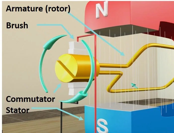
- Continuous motors (DC): Static field, generated by magnets or by windings in the stator; rotate the windings in the rotor.
- Alternating motors (AC): Dynamic field, generated by the interaction between fields generated by current and the rotor.
- Stepper motors: These motors use a sequence of electrical pulses to rotate the motor shaft.
Brushless DC motors offer robustness and reliability and are simple to build and control. A brushless DC motor is an electric motor that converts direct current electrical energy into mechanical energy. It uses magnetic fields to produce motion. Consisting of a permanent magnet rotor and a rotating magnetic field stator, the magnetic field is generated by the stator. The magnets can be permanent (for example, ferrites) in low-power motors and are generated by dedicated windings in medium- and high-power motors, also referred to as wound fields. Power is carried to the rotor by means of rotating collectors and brushes.
DC motors do not need to contact the sliding electrical contacts (brushes) on the motor shaft to function. The switching of the current in the stator windings, and the variation in the orientation of the magnetic field generated by them, occurs electronically. This results in a lower mechanical resistance, eliminates the possibility of sparks forming as the rotation speed increases, and considerably reduces the need for periodic maintenance.
In DC motors, the generated torque is proportional to the current that is passed through the rotor windings. The simplest control via a DC driver acts on the supply voltage. The higher the voltage, the higher the number of revolutions. The driving torque varies as the engine speed changes. They are used a lot in dynamic modelling.
In an AC motor, the generation of the magnetic field is obtained from the difference in angular velocity between the stator currents and those generated in the rotor. The rotor is composed of an electrical circuit consisting of two rings at the ends and the bars that connect them, which are all based on a conductive material. All AC motors generally run without brushes; i.e., they do not need sliding contacts to operate.
The main difference between the two types of motors is speed control. The speed of a DC motor is controlled by varying the current of the armature winding, while the speed of an AC motor is controlled by varying the frequency, which generally occurs with adjustable frequency control.
In addition, the absence of the collector allows the AC motor to reach speeds greater than those of the DC motor and can be supplied with high voltages, which, in the DC motor, is not possible due to the proximity of the collector blades.
There are two types of AC motors: synchronous and asynchronous.
The synchronous motor is a type of electric motor driven by alternating current in which the rotation period is synchronized with the frequency of the supply voltage, usually three-phase. It consists of a rotor (the rotating part that is integrated with the shaft), on which there are several magnetic poles of alternate polarity created by permanent magnets or electromagnets powered by direct current, and a stator with windings, or coils, supplied with alternating current.
Polar expansions of the stator create a rotating magnetic field that drives the rotor. The rotation frequency is related to the supply frequency as a function of the number of polar expansions present in the motor. The power factor of the synchronous motor can be adjusted, and the application of a large synchronous motor can improve operating efficiency without requiring speed adjustment. In recent years, small synchronous motors have been increasingly used in speed-regulation systems.
The asynchronous motor is a type of electric motor driven by alternating current in which the rotation frequency is not proportional to 50/60 Hz; i.e, it is not “synchronous” with it. For this reason, it differs from synchronous motors. In a three-phase motor, the polar expansions are in multiples of three. The asynchronous motor has greater operational efficiency and better-operating characteristics, from the full-load range close to constant speed operation. They also meet most of the transmission requirements in industrial and agricultural machinery.

Fig. 1: The function of a DC motor (Image: Magnetic Innovations)
The stepper motor is a synchronous pulsed direct current electric motor with brushless electronic management, which can divide its rotation into steps. Stepper motors are motors that, unlike all the others, have the objective of keeping the shaft in a steady position. If they are simply powered, they simply stop in a very precise position.
Stepper motors have high torque at low angular speeds. This is useful for accelerating a payload at maximum speed. Moreover, the stepping motors have a high holding torque. This is the torque that, with the motor powered, opposes the rotation. It is generally quite high, and even for small motors, this leads to “self-locking” when the rotor is stationary.
Inside a stepper motor, there are several windings/coils arranged circularly on the stator that operate like electromagnets. The number of phases declared by the manufacturer corresponds to the number of groups of electrically connected coils.
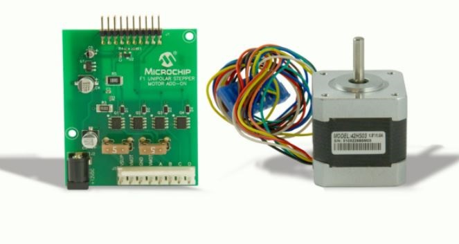
There are two types of stepper motors: unipolar with five to six wires and bipolar with four wires. The difference between the two types is the way in which the electromagnets are connected. There are also hybrid engines that can work in both unipolar and bipolar modes, using motor cables differently (Fig. 2 ).

Fig. 2: Stepper motor with its controller (Image: Microchip)
Controllers
The control of the speed and direction of the motors presupposes the mode of operation of the motor in use and requires different techniques and circuits depending on the type of motor and the different application requirements.
The purpose of a motor controller is to be able to act manually or automatically on the electric motor (start-stop, advance-inversion, speed, torsion, and protection against voltage overloads).
The control of electric motors requires electronic circuits, which until a few years ago were made with discrete components due to the voltages and currents involved. Engine control is at the forefront of research and development activities to achieve efficient microelectronic solutions on two levels: the computational software and power electronics.
At the computational level, in the past, the prevailing technology was digital signal processors (DSPs), which underwent an evolution that led to the realization of various solutions. One example is Microchip Technology’s broad line of low-cost 8-bit PIC and AVR MCUs, as well as high-performance 16-bit dsPIC digital signal controllers (DSCs) that contain innovative motor control PWM peripherals including complementary waveforms, dedicated time bases, and fast 12-bit ADCs.
IGBTs, now in their third generation, represent the basic functionality of electrical power control devices that are well suited to solving complex motor control problems. The latest-generation IGBTs have developed an excellent relationship between switching speed and behavior stability under particularly extreme conditions of use, such as those in the automotive sector in the implementation of inverters to drive electric motors. An example is the 1,200-V IGBT S series from STMicroelectronics. These IGBTs are optimized for low-frequency use (up to 8 kHz), characterized by a low Vce(sat). It is based on third-generation trench-gate field-stop technology.
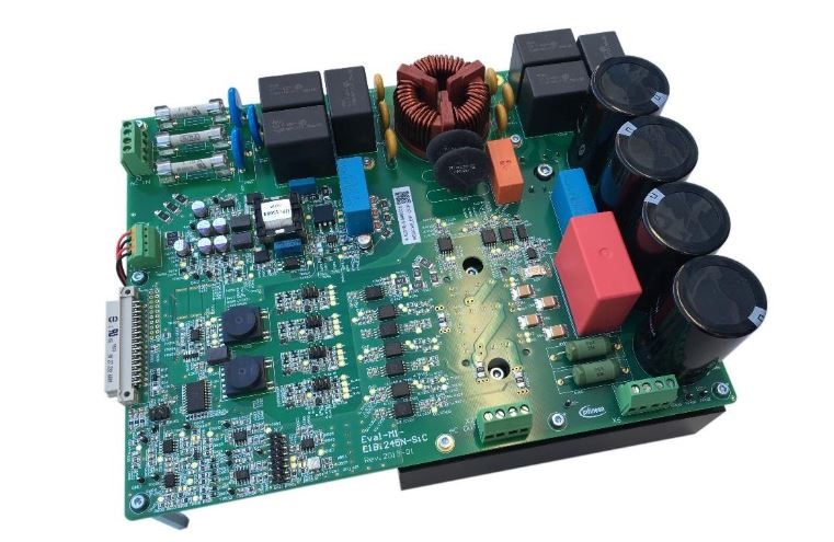
The use of silicon carbide (SiC) devices in motor control and electrical power control applications represents a real moment of innovation thanks to features such as energy savings, size reduction, high integration, and reliability, all of which are particularly sensitive in applications such as automotive and industrial automation control. These devices combine fast silicon-based technology with that of SiC diodes, resulting in a hybrid technological solution. Infineon, for example, has produced integrated power devices as part of a family of components called CoolSiC (Fig. 3 ).

Fig. 3: CoolSiC MOSFET motor drive evaluation board for 7.5 kW (Image: Infineon Technologies)
Conclusion
Motor characteristics, whether it’s a DC, AC, or stepper motor, will determine the design of the motor drive.
The main factors that help define the drive design of brushed DC motors are its advantages, which include simplicity of construction, ease of driving and speed control, and high starting torque. Their speed control can be implemented rather easily by varying the supply current or voltage.
Stepper motors allow for very precise positioning with a very simple control system. They are used in automation, robotics, and computer peripherals (printers, plotters, etc.).
AC asynchronous motors, particularly three-phase motors, are widely used in industry because they can be powered directly from the grid and they are robust, reliable, and economical. However, their use is limited to the simplest movements because they are difficult to control and have poor starting performance.
To select the optimal motor for the application, above all else, it is necessary to establish the resistant torque generated by the load at different speeds and conditions of use (worst case). The resistant torque must be calculated, taking into account the static and dynamic frictions and the inertia of the system on the motor during acceleration and deceleration. Once the torque resistance at different speeds is known, the motor with a torque curve higher than the load torque curve can be selected.
Related article:
Advertisement
Learn more about Electronic Products Magazine


