By Maurizio Di Paolo Emilio, contributing writer
The DC motor is widely used in the field of servo automation and robotics. The operating principle of an electric motor is based on the interaction of two magnetic fields that attract and repel each other.
The two basic parts of the DC motor are the rotor (rotating) and stator (fixed). The stator is a magnetic field inductor, while the rotor is the element subject to the magnetic field represented by a circuit called an armature. Between these two elements, there is a thin layer of air called the “air gap.”
The stator must generate as uniform a magnetic field as possible. Made of lamellar iron, the rotor consists of movable lamellas that are separated by an insulator to increase the electrical resistance and, thus, decrease the parasitic currents induced by magnetization.
The two most common types of DC motors are known as brushed and brushless (BLDC). A BLDC indicates a brushless, permanent magnet electric motor. Unlike a brushed DC motor, it does not need any electrical contacts sliding on the motor shaft to operate.
In a brushed motor, the mechanical contact of the brushes with the electrical contacts on the rotor close the circuit between the power supply and the rotor winding. The rotor and brushes produce a current that continuously changes direction, reversing the magnetic field.
Recommended
Motor control design: an introduction to motors and controllers
In a brushless motor, the current reversal is obtained electronically, through a bank of power transistors (usually IGBTs) controlled by a microcontroller. The main problem in driving them is knowing the exact position of the motor; only in this way can the controller determine which phase to drive. The position of the rotor is usually obtained using a Hall-effect sensor or an optical sensor. In terms of efficiency, brushless motors develop much less heat than an equivalent AC motor due to reduced friction.
Moreover, the windings on the stator in the brushless motor have a good dissipation capacity and allow them to build “smooth” motors without cooling fins. The absence of sparks is essential when the motor operates in environments saturated with volatile chemical compounds such as fuels. In this type of motor, the magnets are positioned on the rotor and are made of special materials that allow a very low inertia. This ensures extremely high precision for both speed and torque, with quick and precise acceleration and deceleration.
BLDC motors offer many advantages over traditional motors. Typically, they provide 15% to 20% better efficiency, require less maintenance because they are brushless, and offer a flat torque curve at all rated speeds.
Recent developments in semiconductor technology, the improvement of permanent magnets, and the growing demand for greater efficiency have led to the replacement of brushed motors with BLDCs in many applications. BLDC motors have found their way into many industries, including home appliances, automotive, aerospace, consumer, medical, industrial automation equipment, and instrumentation (Fig. 1 ).
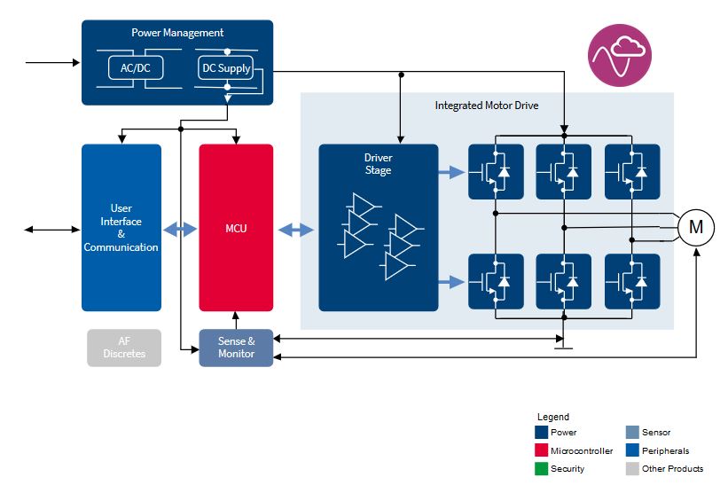
Fig. 1: Example application for brushless DC motor control and driver (Image: Infineon Technologies)
BLDC motors can have single-phase, two-phase, and three-phase configurations; the most common is three-phase. The number of phases corresponds to the number of windings on the stator, while the rotor poles can be any number of pairs depending on the application (Fig. 2 ).
Rotor speed is proportional to the motor’s operating frequency pulse-width modulation (PWM), which is the basic operating frequency to control starting current, torque, and power.
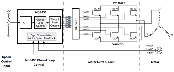
Fig. 2: A typical closed-loop control system for a three-phase BLDC motor includes a controller, driver, and power transistor half-bridge H. (Image: Texas Instruments)
Equivalent circuit of a DC motor
The study of a DC motor and its control involves an accurate analysis of the equivalent model to determine the optimal operating characteristics. Starting from the study of a mathematical model for the DC motor, it is possible to choose the best driver to control the load.
The following equations represent the mathematical model of the rotor, under a simplified hypothesis. It is assumed that the magnetic circuit is linear and the mechanical friction is a linear function of the motor speed (Fig. 3 ).
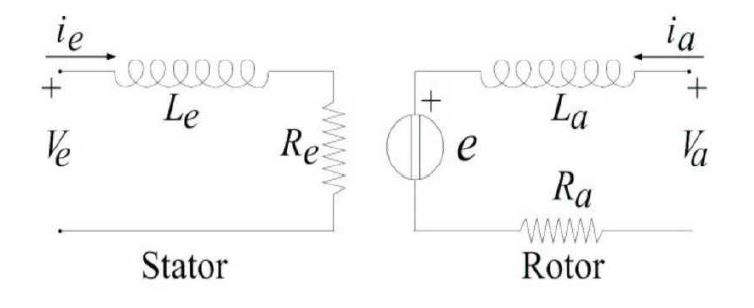
Fig. 3: Equivalent wiring diagram of a DC motor
In a DC motor, magnetic flux is generated by the windings located on the stator. Let’s suppose that the stator has only one polar termination, characterized by an inductance Le associated with its winding and a resistor Re associated with the leaks in the conductor. The equation model of this electrical circuit is:

By transforming the variables in the Laplace domain:
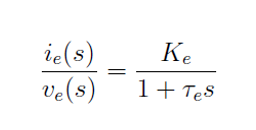
where Ke = 1/Re is the stator gain and τe = Le /Re is the stator time constant.
Similarly, it is assumed that the rotor has only one polar termination characterized by an armature resistance Ra (a few ohms) and an armature inductance La . Furthermore, the effect of the counter-electromotive force e(t), which corresponds to a voltage difference induced by the stator and proportional to the speed of rotation, must be considered in the electrical model of the rotor. The equation associated with the relevant electrical circuit in Fig. 1 is the following:

with va (t) and ia (t), respectively, the armature current and voltage.
Similarly, we will define the rotor gain (Ka) and the rotor time constant (τa). It is possible to define the counter-electromotor force (e) and the mechanical torque cm delivered by the motor as:
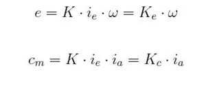
with Ke and Kc being the two constants of the motor called elliptical and torque constant and ω being the angular speed.
The behavior of the mechanical load is almost always non-linear. The linear model of the load can be obtained by equalizing the motor torque cm to the sum of three parameters: a load torque exerted on the motor axis; a parameter proportional to the speed of rotation of the motor according to a coefficient of friction F, and a parameter proportional to the derivative of the rotation speed of the motor according to a moment of inertia J; that is:
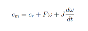
Performing a Laplace transform, we can define two terms: Km , mechanical gain, and em , the mechanical time constant, resulting in the following equation:
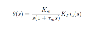
It expresses the direct relationship between position and armature current.
DC motor drivers
The driver is a basic element of BLDC control. It is a power amplifier that produces a voltage output to drive the high-current high-side and low-side IGBT gates of the H-bridge circuit. High side means that the source (in the case of the MOSFET) or the emitter (in the IGBT box) can fluctuate between the ground and higher motor voltage. Low side signifies that the source or emitter is always connected to ground.
A solution such as the BM60212FV-CE2 integrated gate driver from ROHM Semiconductor is ideal for driving a pair of high-side and low-side IGBTs. The device is compatible with 3.3-V or 5-V controller logic signals and provides a variable high-side supply voltage of up to 1,200 V and a maximum gate control voltage of 24 V at the same time. Further enhancements include protection circuits, primarily undervoltage blocking (UVLO) and desaturation protection (DESAT). The UVLO circuit prevents overheating and damage during power-up.
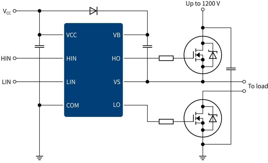
Fig. 4: Typical high-side and low-side driver connection diagram (Image: Infineon Technologies)
Another example is Infineon’s TLE987x family, which addresses a wide range of BLDC applications. It provides an unmatched level of integration and system costs to optimize target application segments. The TLE9873QXW40 device integrates the industry-standard Arm Cortex-M3 core, enabling the implementation of advanced engine control algorithms. Its peripheral set includes a current sensor, a subsequent approximation ADC synchronized with the acquisition and comparison unit for PWM control, and 16-bit timers (Fig. 4 ).
STMicroelectronics’s STSPIN motor drivers for three-phase BLDCs include power drivers in a three-phase bridge configuration and solutions with integrated decoding logic for Hall-effect sensors.
Toshiba has developed an Intelligent Phase Control (InPAC) technology that monitors the current phase (current information) and voltage phase (Hall-effect signal) and provides feedback to the motor current control signal to automatically adjust for optimal phase control to ensure high efficiency. In practice, the phase of the Hall signal is automatically adjusted to match that of the motor drive current. The high efficiency is independent of the speed, load torque, and supply voltage of a motor.
Heat dissipation in a BLDC motor is essential, and its thermal management must ensure high efficiency. The losses can be classified according to the resistance and parasitic capacity of the device.
During switching, the power dissipation of the transistor is proportional to the supply voltage, gate charge (QG), and switching frequency. At a given supply voltage, the increase in switching frequency to increase power density must be offset by a reduction in QG if efficiency is not to be compromised.
The Allegro MicroSystems A89331 sensorless driver is designed to improve thermal efficiency, reduce power consumption, and reduce data center costs. The new power loss brake (PLB) functionality also improves security and reduces material requirements. The unique PLB feature built into the A89331 applies a brake to fans that are not working properly, eliminating extra power consumption and increasing thermal efficiency.
The mechanical structure of an engine could not do its job without electronic hardware control. Energy efficiency, torque, and sensing are the main features to keep in mind when choosing a driver, as well as the type of application. The internal operation accompanied by a mathematical model of a motor allows us to evaluate the operating characteristics easily and then evaluate the choice of the driver.
Related articles:
Motor control design: an introduction to motors and controllers
Part 1 in a series of articles on motor control design starts with an introduction to motors and controllers.
Motor control design: noise reduction in stepper motors
Part 2 in a series of articles on motor control design focuses on how to reduce noise, one of the biggest challenges, in stepper motors.
Advertisement
Learn more about Electronic Products MagazineTexas Instruments


