By Maurizio Di Paolo Emilio, contributing writer
Stepper motors are brushless synchronous electric motors powered by direct current that rotate in steps, keeping the rotor stationary under a specific power supply. A well-defined sequence of PWM pulses sent via electronic drivers turn the stepping motor in one direction.
Stepper motors exhibit a special feature — the ability to rotate the rotor shaft by a few degrees very precisely and without the need for sensors to detect its angular position. In short, a complete revolution of the motor can be divided into a certain number of steps. The stepper motor’s width determines the number of steps.
Inside a stepper motor, there are several windings/coils arranged circularly on the stator that operate like an electromagnet. The stator converts the magnetic field to electric current. The number of steps declared by the manufacturer corresponds to the number of groups of coils (called phases) electrically connected to each other. Within each group, there are several pairs of coils in parallel. Each coil pair is arranged and electrically connected around the stator. Each phase is activated in sequence to allow the motor to rotate, one step at a time.
The stepper motor operates with accurate positioning and speed control by synchronizing with the pulse signal output from the microcontroller to the motor driver. The motor driver reacts to the microcontroller’s signals by delivering power pulses to the stepper motor at the output.
The stepper motor is operated by electrical impulses that feed a part of the stator in sequence. The sequence with which the stators are excited determines the direction of rotation. Through the technique of microstepping, it is possible to obtain a more fluid and linear movement and better positioning. There are different microstepping modes, with lengths from 1⁄3-full-step to 1⁄32-full-step.
Drivers for stepper motors
The stepper motor forms an incremental motion drive. With every command pulse that reaches the system, the motor completes a finite rotation. The rotation is achieved by powering the phases in a given sequence and with a given current direction (Figs. 1 and 2 ).
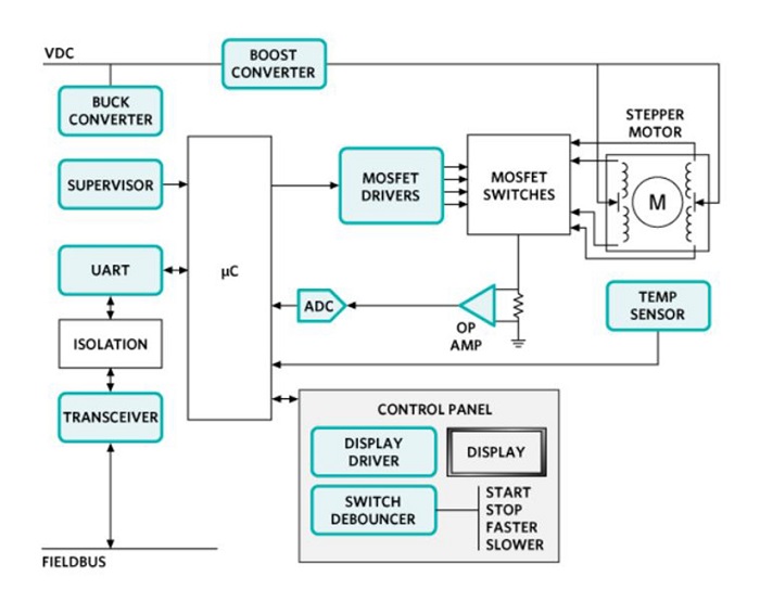
Fig. 1: Electrical diagram of a stepper motor and main components (Image: Maxim Integrated)
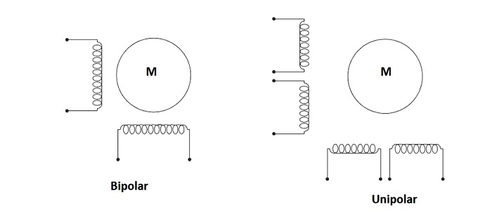
Fig. 2: Generic layout of a bipolar and unipolar motor (Image: Maxim Integrated)
There are different stepper motor configurations and even more ways to drive them. The most common stator configuration is two coils. These are arranged around the stator’s circumference in such a way that when driven with square wave signals, the motor turns. To turn the motor in the opposite direction, simply reverse the ratio between Phases A and B of the signals.
The main applications for stepper motors are robots, office automation (OA) equipment, and medical/nursing equipment, which require motors with superior precision motor control and better resistance to environmental influences. Motor control solutions such as resolvers and encoders are used to optimize the movement and guarantee the correct position of the motors.
Stepper motors with a resolver enable high-precision motor control even in harsh environments with heat, dust, or vibration and maximize the available torque. The resolver is a type of inductive displacement transducer — an electromechanical device for the measurement of angular displacement. The device detects the variation of magnetic induction flux in the solenoid.
As an example, Renesas Electronics Corp. has developed a new resolver-to-digital converter (RDC) that supports MinebeaMitsumi’s new stepper motors, as well as control driver software for controlling the RDC with a 32-bit RX MCU. Renesas and MinebeaMitsumi have developed sensor-based stepper motors and motor control solutions that meet extreme-precision application requirements in harsh environments (Fig. 3 ).
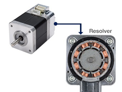
Fig. 3: Stepper motor with a resolver (Image: Renesas)
Toshiba Electronic Devices and Storage Corp.’s driver solutions incorporate active gain control (AGC) technology, which detects the motor load torque and automatically optimizes the motor drive current. This prevents a motor from slipping while simplifying high-efficiency motor control.
Maxim Integrated offers the MAX15024/ MAX15025 MOSFET gate drivers that are suitable for high-frequency and high-power circuits capable of operating at frequencies up to 1 MHz with large capacitive loads. The MAX15024 can absorb a peak current of 8 A and generate a peak current of 4 A. An integrated adjustable LDO voltage regulator provides gate-drive amplitude control and optimization.
Infineon Technologies AG offers the TLE 8444SL, a protected quad-half-bridge IC for automotive and industrial motion control applications based on the company’s intelligent mixed-technology SPT that combines bipolar and CMOS control circuits with DMOS power devices. The PG-SSOP-24-7 package is advantageous, as it saves space and costs on the PCB. Integrated protection and diagnostic functions improve system reliability and performance.
Microstepping
Stepper motors can perform positioning with higher resolution than a full step when combined with drivers capable of electronically splitting the mechanical step of the motor. Microstepping is used to achieve higher stepper motor resolution, offering smoother movement at low speeds.
For example, a stepper motor with a pitch angle of 1.8° results in a rotation of 200 steps (resolution) for each complete revolution of the motor (360 ÷ 1.8). This discrete movement causes the motor rotation to not be perfectly smooth.
A reduction in the size of the motor steps using the microstepping technique can deliver smoother movement at low speeds. The microstepping control divides each complete step into smaller values: For example, a 1.8° pitch can be divided up to 256 times, providing a pitch angle of 0.007° per revolution.
This data indicates the resolution of the position and not its accuracy, which depends on the electromechanical precision of the engine, as shown in the engine’s specifications (5% for good-quality hybrid engines).
Microstepping uses pulse-width–modulated (PWM) voltage to control the motor current. While the current in one winding increases, the other decreases. This results in a smooth movement. Microstepping is sometimes considered a good alternative to mechanical gears because it does not introduce kickback into the system or reduce the maximum system speed (Fig. 4 ).
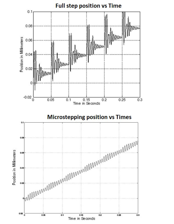
Fig. 4: Microstepping significantly reduces position oscillation in the motor. (Image: Dover Motion)
Microstepping makes it possible to obtain a wide range of intermediate positions between two steps. The closer the rotor is to a position of equilibrium, the greater the current will be in the corresponding phase.
Microstepping is more energy-efficient and uses smaller, more frequent pulses, allowing stepper motors to reach slightly higher speeds than usual. The compromise is that the motor torque is often reduced slightly.
There is a variety of integrated microstepping motor drivers available in the market. One solution is Allegro MicroSystems’ A4988 DMOS microstepping motor driver with an output drive capacity of up to 35 V and ±2 A. The A4988 is supplied in a surface-mount, 5 × 5-mm, QFN package and offers the ability to operate in slow or mixed-decay mode. Mixed-decay current control reduces audible motor noise, increases pitch accuracy, and reduces power dissipation (Fig. 5 ).
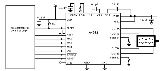
Fig. 5: Typical application diagram (Image: Allegro Microsystems)
Another example is the L6470H dSPIN driver for microstepping from STMicroelectronics, built on analog mixed-signal technology. The microstepping driver integrates a dual low RDS(on) DMOS bridge complete with accurate current-sensing circuitry and overcurrent protection. The digital control core is programmed through a dedicated set of registers. It also includes protection circuitry, delivering a fully protected design as required by the most demanding motor control applications (Fig. 6 ).
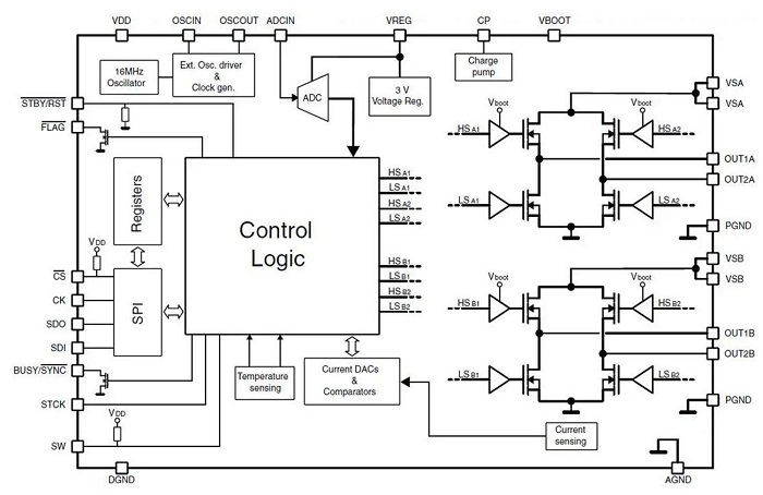
Fig. 6: Circuit diagram of the L6470H (Image: ST Microelectronics)
The DRV8880 and DRV8881 motor drivers with AutoTune technology developed by Texas Instruments Inc. eliminate the complex and tedious manual adjustments of the circuit, which often require several weeks of design and optimization, by automatically tuning the stepper motors for optimal current regulation performance while compensating for motor variation and aging effects.
Drivers with AutoTune technology are able to configure off-time PWM modulation with microstepping above 1/16 step. They can be connected in parallel to obtain higher output currents, and in the case of the DRV8880, it has an internal DAC for load torque control.
Conclusion
Stepper motors can be controlled with a digital circuit, such as a microcontroller, with great ease and precision without requiring devices that detect its angular position. Microstepping is used to achieve higher resolution, energy efficiency, and smoother motion at low speeds. It delivers a more linear operation, eliminating step noise and resonance issues.
However, the use of microstepping can reduce torque by up to 30%. Thus, it will be necessary to evaluate the electrical specifications of the motor to select the right driver.
Related articles:
Motor control design: An introduction to motors and controllers
Part 1 in a series of articles on motor control design starts with an introduction to motors and controllers.
Motor control design: Noise reduction in stepper motors
Part 2 in a series of articles on motor control design focuses on how to reduce noise, one of the biggest challenges, in stepper motors.
Motor control design: Noise reduction in stepper motors
Part 3 in a series of articles on motor control design focuses on the selection of DC drivers.
Advertisement
Learn more about Electronic Products MagazineInfineon TechnologiesMaxim IntegratedRenesas Electronics AmericaTexas InstrumentsToshiba America Electronic Components


