For any designs that deal with large motors, isolation is a desired characteristic for both control and sense loops. Turn on, turn off, changes in load, changes in power, and unexpected events can backfire as mechanical jerks and jolts as well as electrical spikes and surges. Such events can be disastrous for low-voltage electronics, especially if they couple to power supplies.
As a result, power supplies used for sensor bias are isolated from the power supplies powering the control electronics. Drivers used to power motors are triggered by signals that are isolated from the control electronics. And, sensors that monitor motor currents and voltages are isolated from the digital- (PWM or serial), or analog- (A/D) fed signals on the microcontroller in charge.
Another beneficial isolation comes with several types of shaft encoders. These can be mechanically coupled to the actual rotating shaft of a motor or powertrain assembly, or, they can passively monitor rotation through optical, magnetic, or even resistive techniques.
For the most part, resistive techniques are a thing of the past. These techniques use a mechanical wiper to make contact with a circular rheostat that may work well at first, but can eventually suffer from frictional wear, mechanical vibration distortions, temperature drift, and moisture. On the plus side, they are inherently nonvolatile absolute reporters of position. If power is lost and comes back, the position is known by reading the resistance. Because of this, the resistance creates an absolute encoder.
Magnetic encoders that use Hall effect technology can be an effective solution as well. As long as resolute magnets are embedded in a part of a rotating shaft, a detector can easily pick up a pulse as the shaft’s magnet rotates past the sensor. These can be classified as switched encoders with output resolution ranges from 50 pulses per revolution to 3,600 pulses per revolution. These work well as long as the magnet does not demagnetize, attract debris, or induce eddy currents in nearby electronics. One major drawback of magnetic encoders is that, unless there is a rather precise and expensive multi-magnet shaft, the result is only one pulse per revolution. Alternatively, designers can always add a geared larger diameter shaft that can more easily fit magnets, but of course, this adds expense and size.
Optical encoders can solve all these problems while remaining isolated. Photo interrupter types use a mechanically coupled timing wheel that either blocks or passes light, usually infrared light. These are also called transmissive encoders. Timing wheels can have multiple cutouts, so an engineer could get pulses every 30 degrees with a 12-hole timing wheel, for example.
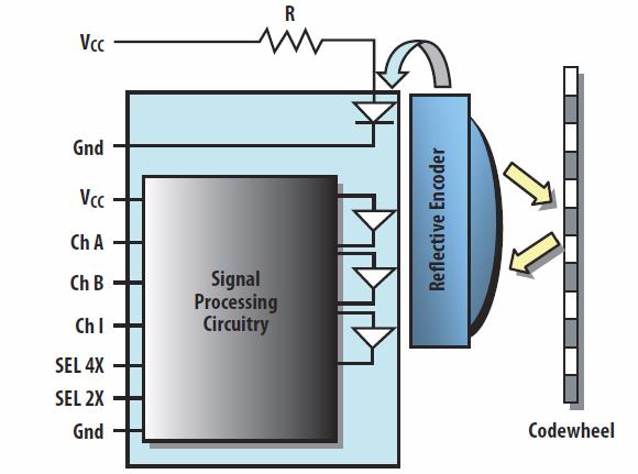
Reflective encoders involve a similar photo technique, using a coplanar emitter and detector that can reflect from a timing wheel or coded strip. These have the benefit of living inside a sealed unit or shell since nothing has to traverse through them.
If space is not a constraint, these techniques can work with very high accuracies. The further out one moves from the center of rotation, the higher the attainable resolution. For example, an engineer may be able to get 30-degree resolution by fitting 16 holes in a small 2-inch timing wheel. However, he or she could easily get 1.4 degrees of resolution by fitting 256 holes around a 4-inch timing wheel.
Sealed and finished rotary units also use photo interruption techniques to accomplish this incremental-style encoder. Sealed incremental rotary encoders will typically use two timing wheels and deliver a quadrature output. The phase relationship can be used almost instantaneously to determine or verify direction as well.
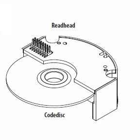
One alternative to using incremental encoders is to use an absolute encoder like the AEAT-9000-1GSH1 from Avago Technologies. These are also known as single-turn encoders since all the resolution manifests in a single turn. These encoders provide a parallel output representative of position, in this case 17 bits. Inside, a code disk passes by a read head that reads binary patterns (gray codes) representative of the absolute position. These can be hermetically sealed and the resolution will depend on the diameter of the code wheel used.
Absolute encoders deliver a parallel position indication that is the exact position of every change in position. A micro, FPGA, or counter-array is not needed to ascertain location.
Advertisement
Learn more about Avago Technologies


