By Tami Pippert,
High-Speed Digital Marketing Programs Manager
Keysight Technologies, Inc.*
www.keysight.com
While multi-level signaling techniques like PAM-4 have been implemented for some time in telecom and long-haul optical applications, implementation of PAM-4 in the data center space creates a very different set of challenges, given the need to create much more cost-effective serial data links. PAM-4 is one of the enablers in the next generation of data rates in data center networking and IT infrastructure (what will really become 400G Ethernet), but it is also going to show up in other places as well.
Understanding of the causes and mechanisms that impair link performance is growing daily. As this new science becomes better defined in the industry, new measurements will be required to characterize the output of transmitters, and new stress impairments will be required to test receiver inputs to successfully deploy PAM-4 in new products.
Meet PAM-4
The PAM-4 protocol has four distinct amplitude levels: -3, -1, 1, and 3 (fig. 1 ). As a result, PAM-4 eye diagrams have three distinct vertical openings, so-called “eyes”, corresponding to the signal levels, instead of just the single eye that NRZ signals produce. The additional vertical levels allow PAM-4 to provide 2 bits of information, versus an NRZ signal's single bit, at the same Baud rate (28 GBaud PAM-4 = 56 Gb/s). So, from a frequency domain perspective, PAM-4 requires half the bandwidth of NRZ for the same data transmission rates.
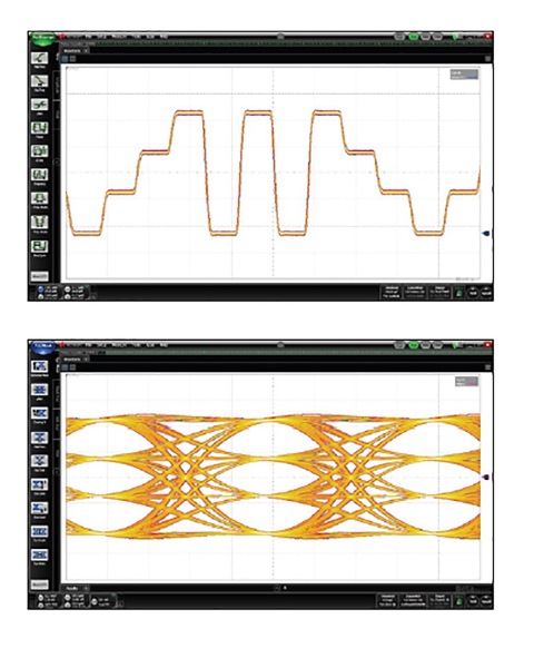
Fig. 1: PAM-4 has four distinct amplitude levels (top) that result in a three-opening eye diagram (bottom).
The use of multi-level signaling with PAM-4 requires innovative tools designed to deal with multiple signaling levels, as well as other PAM-4 test challenges, including clock recovery, decision feedback equalization (DFE), and reductions in the signal-to-noise ratio. The following is a quick overview of the challenges created as a result of broader PAM-4 adoption.
PAM-4 Simulation
Typical PAM-4 communications system configurations for transmitter (TX), channel, and receiver (RX) can be chip-to-chip, chip-to-module (electrical or optical), or electrical backplane. Development of these high-performance components, modules, and networks requires sophisticated test and measurement techniques for interface interoperability and test validation. Because it is new, PAM-4 400G Ethernet development has very little historical technology or engineering experience to reference, which makes PAM-4 system simulation very valuable. New considerations for tests and end-to-end link simulation will be essential to verify PAM-4 compliance and ensure interoperability. The ability to test and rectify effects of interference at the higher data transmission rate and to research the new circuit, module, and network technology required for PAM-4 designs depends on successful PAM-4 simulation. Electronic Design Automation (EDA) tools for signal integrity will enable designers to address the simulation-measurement correlation and workflow for Ethernet PAM-4 and NRZ.
PAM-4 measurement solutions
Measurement and simulation challenges for PAM-4 are similar to each other. The key challenges facing engineers today are clock recovery (CR), eye skew, and noise. With PAM-4, there are new complexities that increase measurement challenges. Impaired links can be related to implementation of clock recovery, and closed eye challenges such as skew, compression, and nonlinearity (fig. 2 ). As the PAM-4 technology continues to advance and knowledge of PAM-4 challenges and solutions grows, new measurements will emerge to characterize transmitter (Tx) outputs and new stress impairments will be developed to test and characterize receiver (Rx) inputs.
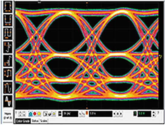
Fig. 2: Higher data rate transmissions cause a change in signal characteristics and additional error correction techniques are needed to maintain an open eye. Non-linearity or amplitude compression can alter the eye height of different transition eyes causing a linearity error due to a lower signal to noise ratio of the lower transitions.
Output transmission (Tx) characterization
Output (Tx) testing verifies that the output parameters meet or exceed the standard requirements including eye parameters and jitter measurements. The standard Transmitter Linearity Test Pattern and Quaternary PRBS13 Test Patterns enable PAM-4 signals to be tested for linearity and key eye parameters. There are two different types of PAM-4 receivers being considered for development; a slicer level based receiver where eye height/width are important, or an ADC based receiver where level variation in constellation form is most important. The Quaternary test pattern can be used to verify transmitter outputs for either receiver design.
Transmitter (Tx) characterization can be measured by a sampling oscilloscope with PAM-N analysis software. Due to their hardware architecture, sampling oscilloscopes have a much lower noise floor than real-time oscilloscopes, and as a result, will typically yield a more accurate characterization of a PAM-4 signal. Tx characterization can also be measured using a real-time oscilloscope, which is best for troubleshooting and single shot events. The real-time oscilloscopes provide the fastest sample rate, large record length, and don’t require repetitive signals to generate pattern waveforms.
Input receive (Rx) characterization: Input testing verifies that the receiver is able to detect correct bits along with impairments from a worst case channel. Receivers are more susceptible to linearity and skew problems. The inherent ISI in the PAM-4 eye requires receivers to be much less sensitive to pattern dependent jitter. Since bit error can be seen on a noisy channel if not balanced, receiver equalization is required to balance the gain between CTLE DFE. Inherent ISI requires receivers to be less susceptible to pattern dependent jitter. As PAM-4 receiver technology progresses, new types of stress impairments will need to be developed for testing the receiver inputs.
An alternative to traditional bit error ratio testers for PAM-4 is an arbitrary waveform generator (AWG). New AWGs serve as a solution for communication signals with the ability to generate any amplitude modulated signal such as PAM-8, coherent, OFDM and QAM-N. Stress types including jitter, interference, skew, linearity and more can be easily generated.
As the demand for increasing data rates drives continued increases in speed from 100G to 400G, many new design and measurement challenges will be presented. From early design simulation and characterization of outputs, to creating new stress types for input testing as the standards evolve, there are many design and test implications associated with PAM-4.
[Ed. note: for more on this topic, visit www.keysight.com/find/PAM-4.
*Keysight Technologies Inc., formerly Agilent Technologies electronic measurement business
Advertisement
Learn more about Keysight Technologies, Inc.


