Preventing thermal runaway resulting from failed power FETs improves a lighting system’s safety and performance
BY PHILIPPE DIFULVIO
Application Engineering Manager
and FARAZ HASAN, Sr.
Global Strategic Business Manager for Industrial, Appliance, Lighting
TE Circuit Protection
www.circuitprotection.com
Most industrial and consumer electronics incorporate thermal protection devices to prevent damage caused by overheating and improve reliability and safety. The heat generated by resistive and inductive loads, power capacitors, and current drivers to MOSFETs, switches, and relays presents significant challenges to engineers charged with designing in reliable, safe thermal management.
In recent years, a variety of innovative technologies have emerged to help designers of electrical and electronic applications implement thermal protection. The objective is to protect the application and the end user from catastrophic thermal events by interrupting electrical current flow when a component or board area is heated to a specific rated temperature.

Conventional solutions
Traditional thermal protection devices are available in a variety of shapes, sizes, and technologies to help protect equipment from damage caused by thermal events. Two notable devices are the thermal fuse/thermal cutoff (TCO) and the thermal switch. Both provide wide-ranging and specific temperature activation characteristics in both AC and DC applications and can be specified as bolt-in, clip-on, pig-tail, or lead-type configurations. However, these devices can complicate design-in and manufacturing processes. Careful handling procedures must be adhered to in order to guarantee that they perform as expected.
Thermal fuses typically contain a component that is temperature sensitive, such as a low-temperature alloy or a plastic/wax pellet, which holds a spring contact mechanism. The device is normally closed and opens when activated at a given maximum, or trip, temperature. These devices are also non-resettable and must be replaced after they trip.
Thermal fuses require special handling in the manufacturing process. If they are to be soldered, or require wire extensions to be soldered or welded to the leads, a heat-sink must be attached to the lead to conduct heat away from the temperature-sensitive alloy so as to not activate it or limit the effectiveness of the device before it is to be used in its intended application.
Another common thermal protection device is the thermal switch. These devices are designed for multiple uses and can be configured to be normally-open or normally-closed. When a specific trip temperature is reached the thermal switch activates and opens like a thermal fuse to stop the current flow. Likewise, when designed to close during a thermal event, the thermal switch can be used to activate a secondary airflow device, such as a fan, to cool the application. When a predetermined temperature is reached the device will revert to its pretripped state, normally open or normally closed.
One limitation of traditional TCOs is that they are not surface mount or reflowable like standard semiconductor products and require manual application. Thermal cut-offs also exhibit lower current ratings, limited dc rating (ac rated), vibration sensitivity and installation sensitivity. Due to repeated operations at temperatures close to but below their calibration temperatures, or as a result of excessive thermal waves across the case and the leads of the TCO, nuisance trips may occur because of pellet shrinkage.
Thermal fuses, unlike electrical fuses, react only to excessive temperature, not excessive current — unless the excessive current is sufficient to cause the thermal fuse itself to heat up to the activating temperature due to I2 R effects. Thermal fuses are also intended as a fail-safe or as an added safety backup that will activate when other electrical safety measures such as circuit breakers or traditional fuses fail. Thermal fuse operating characteristics can also change over time from self-heating effects or from operating under high current loads.
With applications continually moving towards more compact surface-mount designs, the major limitations of traditional thermal protection devices are that they are not available in surface-mount configurations, require costly manual application processes, and, in the case of traditional TCOs, they may fail short.
Reflowable thermal protection device
TE Circuit Protection has introduced a surface-mount, thermal protection device that is pick/place compatible and can be designed-in and reflowed on a PCB, utilizing standard surface-mount lead (Pb)-free reflow manufacturing processes over a broad range of device activation temperatures.
The reflowable thermal protection (RTP) device is set to withstand the demanding environmental, life, and reliability requirements of automotive and industrial applications, including shock, vibration, temperature cycling, and humidity exposure. Once the reflow process is complete an arming procedure is all that is required in order for the device to be ready to activate at its predetermined trip temperature.
Another area where thermal protection may be desirable is the PCB trace itself. When PCB traces are electrically stressed, hot-lines begin forming on the trace causing delamination. Leaving PCB traces unprotected can result in a catastrophic thermal event. When properly selected and thoroughly tested in the end-application, the RTP device protects PCB board traces from damage caused by overheating.
Thermal runaway in dimmer apps
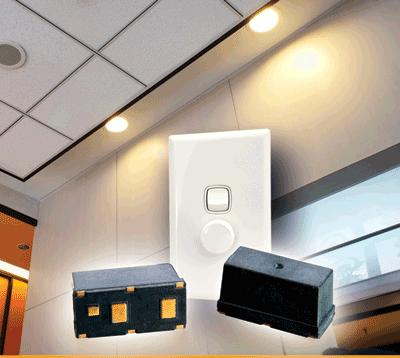
Universal dimmers, used with increasingly popular LED lighting systems, are subject to power FET and MOV failure — which can lead to thermal runaway and potentially catastrophic events. Because most lighting dimmers are embedded in the wall of a house or building, providing robust, reliable circuit protection is a primary design consideration.
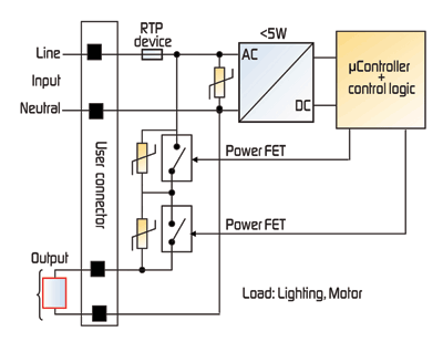
Two power FETs are typically used to dim the lights and set the speed of the motor in universal dimmers. Traditionally, metal oxide varistors (MOVs) have been used to protect the FETs from damage from overvoltage events such as lightning and other surges. Today, however, the need for safety is driving designers to also employ thermal cutoff devices to sense overtemperature events as a means for providing secondary thermal protection. If a power FET fails in resistive mode or an MOV fails due to an increase of the leakage current, either of which can lead to thermal runaway, the thermal device activates to shut down power and prevent catastrophic events.
Seen in Fig. 1 , the RTP device can be placed in series and in intimate thermal contact with the power FET to help the application against damage from elevated FET temperatures. If the FET fails in resistive mode and overheats, the RTP will activate to help prevent thermal runaway.
In this example the RTP device (model RTP-140) is rated to activate at 140°C. Once it has been reflowed onto the PCB a simple arming procedure is all that is needed to ready the device. Once installed, it will activate at 140°C to interrupt the current if FET failure results in overtemperature conditions, opening before the solder melt point of 220°C. This device is useful for, but not limited to, LED lighting and appliance electronics and can be reliably used and reflowed into areas of high-power components on the PCB wherever thermal protection is needed to help protect against damage caused by thermal runaway.

Fig. 1: The RTP device can be placed in series to help protect the power FET.
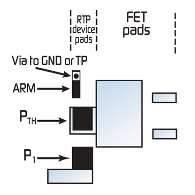
Figure 2 shows how proper thermal coupling with the RTP device can help protect a specific component or application. Intimate thermal contact with the potential heat source is critical to achieve the desired performance. The performance of the RTP device is based on the expectation that the PTH pin of the RTP shares a copper mounting pad with the primary thermal pin or heat sink of the FET or other component’s heat-sinking pin(s)/tab(s).

Fig. 2: Proper thermal coupling of an RTP device.
The RTP device is a convenient, cost-effective alternative to traditional thermal protection devices. It allows use of standard surface-mount production methods, obviating the need for special assembly procedures and their associated costs. These characteristics make it suitable for LED lighting systems and appliance electronics. The device also helps protect power components in IT servers, telecom power, and automotive electronics. ■
Advertisement
Learn more about TE Circuit Protection Group


