Server power supplies are becoming firmware-driven as digital control replaces analog control. This means that firmware upgrades can improve performance and add new features, after the power supply is installed. It is easy to upgrade the firmware by turning the power supply off and restarting it with the new firmware. Datacenters, however, want to maximize their server uptime with on-the-fly upgrades, without turning off the power supply. This poses some unique challenges.
There are several challenges with addressing this issue. For instance, the firmware is stored in a flash module. Most microcontroller flash modules cannot be written to and executed from at the same time. This makes it impossible to load a new program into the flash while simultaneously running the power supply program from flash.
There must be enough system horsepower available to download the new firmware and to run the power supply at the same time. Also, the system hardware and firmware must support the reconfiguration of the desired features.
Finally, power supply control and protection from faults must continue during the switching process.
One way to address these challenges is to use two separate, independent, remappable flash modules and dedicated hardware for the fault-handling and power supply control. Also, the designer must be careful when designing the hardware and firmware for easy reconfiguration. Skillful firmware design takes advantage of hardware fault protection by overlapping the old and new fault protection methods and by making the switch as fast as possible.
Two flash modules
An example of such a device is the UCD3138064, which adds a second, completely independent remappable block of program flash. The first block executes the old version of firmware while the new version is downloaded to the second block. The active block is mapped to location 0, and the inactive block is mapped to 0x8000. When the firmware upgrade occurs, the blocks are switched. It doesn’t matter which block the new version is written to, all firmware versions are identical. The interrupt vectors start at location 0, so the active version provides them, making interrupt handling very efficient.
Dedicated power supply hardware
Most of the power supply control and fault handling is done, not by the microprocessor, but by dedicated state machines. These machines handle output voltage monitoring, proportional-integral-derivative (PID) compensation, and pulse-width modulation (PWM) generation, as well as high-speed fault handling. They are configured and started by the processor. State changes such as going from idle to ramp up, from ramp up to run, run to ramp down or shut down, and so on, require some reconfiguration, but generally the processor is only monitoring the system. This leaves plenty of processor horsepower available to handle the download of the new firmware. And it means that the 5 μsec. absence of firmware control during the block remapping does not risk power supply damage.
Support for reconfiguration
Easy reconfiguration is achieved primarily by the design of the state machines. Many of the normal configuration values, like filter coefficients, gains, switching frequencies, fault thresholds, fault configurations, dead times, and so on, can be reconfigured without any need to change the firmware. The connections between input analog-to-digital converters (ADCs), control filters, and PWM outputs also can be changed on-the-fly. Firmware functions can be enabled and disabled. Of course, if the firmware isn’t present or if the existing firmware doesn’t support a specific hardware reconfiguration, a new firmware version is needed.
If a complete topology change is desired, which is unlikely, say from phase-shifted full bridge to hard switching full bridge, the differences might be too drastic to change on-the-fly. While some cases probably can be supported, others may not be so easy.
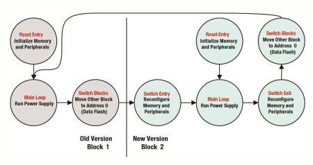
The firmware must be designed with the capability to download the new version and with the proper entry and exit points to support on-the-fly switching. Fig. 1 shows the firmware organization for old versus new configuration.

Fig. 1: State diagram for on-the fly switching
The reset entry states are the states entered at system power up. They initialize the whole system. The special effort for on-the-fly switching comes in the switch entry and switch exit blocks in the new version. Here the firmware reconfigures only the things that change between versions.
On-the-fly switch example
Here is an example of a real on-the-fly switch. The new firmware version provides several added features. The old version uses simple hardware over-current protection (OCP). If the current is too high, the power supply shuts off. The new firmware adds constant power (CP) mode, which drops the output voltage to limit power. This keeps the thermal load within a safe range, but enables the power supply to keep running. The cycle-by-cycle (CBC) current limit hardware is enabled as a hardware support feature for the constant power firmware. CBC limits the current on each switching cycle, but does not shut off the power supply. Also, PFC communication is added so that the server has visibility out to the AC line conditions, such as input current and input power.
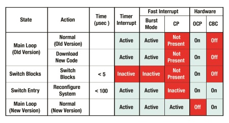
The switch timeline is shown in Fig. 2 .

Fig. 2: Example timeline for on-the-fly switching
The first column shows the system state, while the second shows the action taking place. The timer interrupt is shown because slower faults, such as temperature faults, are handled by the timer interrupt function. Note that even these faults are only ignored for 5 µsec while the blocks are being switched. After that, interrupts are re-enabled. In the switch entry function, the OCP hardware fault is only disabled after the CBC hardware protection is enabled. This ensures continuous hardware fault protection. Once the CP is configured, it is enabled. The whole reconfiguration process takes less than 100 µsec.
Two independent re-mappable flash blocks with powerful, reconfigurable peripherals are used. Carefully written firmware makes on-the-fly firmware upgrades a reality for isolated power supplies.
About the Author
Ian Bower is a firmware designer for Texas Instruments where he is responsible for firmware definition, design, documentation, and training for digital power controllers. Ian received his Bachelor of Science in Engineering from the Illinois Institute of Technology, Chicago, Illinois. He can be reached at .
Advertisement
Learn more about Texas Instruments


