Optimizing a mobile robot’s navigation performance
Accuracy in managing position and motion is key to useful, reliable autonomous operation of mobile robots
BY MARK LOONEY
iSensor Application Engineer
Analog Devices
www.analog.com
Ground-based robots are typically used for missions where direct human involvement is too expensive, too dangerous, or just ineffective. Often, the robots must be able to operate autonomously, using navigation systems to monitor and control their motion when moving from one location to the next, and when accuracy in managing position and motion is key to useful, reliable autonomous operation.
MEMS (micro-electromechanical system) gyroscopes provide a feedback sensing mechanism that can be very useful in optimizing navigation system performance. The Seekur robot system (see Fig. 1 ) is an example of an autonomous system that employs advanced MEMS devices to improve navigation performance.
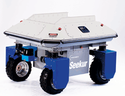
Fig. 1: The Seekur system developed by Adept MobileRobots (www.mobilerobots.com) is an autonomous systems employing advanced MEMS sensors.
A robot navigation overview
A robot’s movement typically starts with a position change request from the central processor managing the progress of the robot’s overall mission. The navigation system begins executing a position change request by developing a trip plan or trajectory.
The trip plan considers available paths, known obstacle locations, robot capability, and any relevant mission objectives. (For example, delivery time can be critical for a specimen delivery robot in a hospital.) The trip plan is fed into a controller, which produces drive and direction profiles for navigational control. These profiles result in motion and progress with respect to the plan. The motion is typically monitored by a number of sensing systems, each of which produces feedback signals; the feedback controller combines and translates them into updated trip plans and conditions.
The key steps in developing a navigation system start with a good understanding of each function, with particular emphasis on its operational goals and limitations. Each function typically has some clearly defined and easily executed aspects, but also offers challenging limitations that need to be managed. In some cases, this process can be iterative, where identifying and dealing with limitations enables new opportunities for optimization.
As an example, the Adept MobileRobots Seekur is an autonomous robot that has a four-wheel drive system, with independent steering and speed control for each wheel, to provide the flexibility to move the platform in any horizontal direction. It’s inertial navigation system (INS) is similar to the one shown in Fig. 2 .
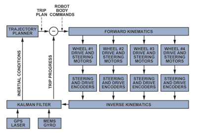
Fig. 2: The Seekur’s navigation system uses GPS, laser sensing, and MEMS gyros to independently control each of the system’s four wheels.
Forward control
As seen in Fig. 2, forward control is achieved by issuing robot-body commands These commands are essentially error signals derived from the difference between the trip plan provided by the trajectory planner and trip progress updates produced by the feedback sensing system.
The commands are fed into the inverse kinematics system, which translates the robot body commands into steering and velocity profiles for each individual wheel. These profiles are calculated using Ackermann steering relationships, which incorporate tire diameter, surface contact area, spacing, and other important geometrical features.
Ackermann steering principles and relationships enable these robot platforms to create electronically linked steering angle profiles similar to those of the mechanical rack-and-pinion systems used in many automotive steering systems. Incorporating these relationships remotely, without requiring the axles to be mechanically linked, helps minimize friction and tire slip, provides the benefits of reduced tire wear and energy loss, and allows motion not possible with simple mechanical linkages.
Feedback sensing and control
Each wheel has a drive shaft that is mechanically coupled to its drive motor through a gear box and—through another gear box — to an optical encoder, which is an input to the odometry feedback system. The steering shaft couples the axle to another servo motor, which establishes the wheel’s steering angle. The steering shaft also couples to a second optical encoder through a gear box — which provides another input to the odometry feedback system.
The navigation system uses an extended Kalman filter to estimate the pose of the robot on the map by combining data from multiple sensors. The odometry data on the Seekur is derived from the wheel traction and steering encoders — which provide the translation — and a MEMS gyro, which provides the rotation.
Odometry
The odometry feedback system estimates robot position, heading, and speed using optical-encoder measurements of drive- and steering shaft rotation. Figure 3 provides a graphical reference and relationship for translating the rotation count of the drive shaft’s optical encoder into linear displacement (position) changes.
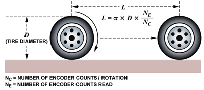
Fig. 3: The odometry system determines linear displacement using encoder readings in accordance with the relationship shown above.
The drive-axle and steering-shaft encoder measurements for each wheel are combined in the forward-kinematics processor, using the Ackermann steering formulas, which produce heading, turn rate, position, and linear velocity measurements.
The advantage of this measurement system is that its sensing function is directly coupled to the drive and steering control systems, so their state is accurately known. However, its accuracy in terms of the actual speed and direction of the vehicle is limited unless reference to a set of real-world coordinates is available. The primary limitations, or error sources, are in the tire-geometry consistency (the accuracy and variation of diameter in Fig. 3) and breaks in the contact between the tire and the ground surface. Tire geometry is dependent on tread consistency, air pressure, temperature, and weight — all conditions that can change during normal robot use. Tire slip depends on turn radii, velocity, and surface consistency.
Position sensing
The Seekur system uses various range sensors. For indoor applications, it employs a 270° laser scanner to build a map of its environment. The laser system measures object shapes, sizes, and distance from the laser source using returned-energy patterns and signal-return times.
When in its mapping mode, it characterizes its workspace by combining scan results from many different positions in the workspace (see Fig. 4 ). This produces a map of object locations, sizes, and shapes, which is used as a reference for run-time scans.
When used in conjunction with the mapping information, the laser scanner function provides accurate position information. If used by itself, it would bear limitations that include the stop time for scans and an inability to manage a changing environment. In a warehouse environment, people, lift trucks, pallet jacks, and many other objects change position often, which could potentially impact speed to a destination and, indeed, accuracy of achieving the correct destination.
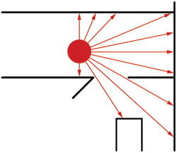
Fig. 4: Laser sensing permits mapping of a surrounding environment such as the hall-door-room-cabinet arrangement shown here.
For outdoor applications, the Seekur uses global positioning systems (GPS) for position measurements. These systems use flight times of radio signals from at least four satellites to triangulate a position on the earth’s surface.
When available, such systems can provide accuracy to within 1 m. However, they are limited by the line of sight requirements, which can be impeded by buildings, trees, bridges, tunnels, and many other types of objects. In some cases, where outdoor object locations and features are known (such as urban canyons), radar and sonar can also be used to supplement the position estimates during GPS outages. Even so, effectiveness is often limited when dynamic conditions exist, such as cars passing by or construction.
MEMS angular rate sensing
The MEMS gyroscope used in the Seekur system provides a direct measurement of the Seekur’s rate of rotation about the vertical, or yaw, axis, which is normal to the earth’s surface in the Seekur navigational reference frame. The mathematical relationship for calculating a relative heading (Eq. 1) is a simple integration of the angular rate measurement over a fixed period (t1 to t2 ):

One of the key advantages of this approach is that the gyroscope, being attached to the robot frame, measures the vehicle’s actual motion without relying on gear ratios, backlash, tire geometry, or surface contact integrity. However, the heading estimate does rely on sensor accuracy, which is a function of the following key parameters: bias error, noise, stability, and sensitivity.
Fixed bias error, ωBE , translates into a heading drift rate, as shown in Eq. 2:
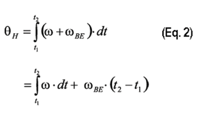
Bias error can be broken down into two categories: current and condition-dependent. The Seekur system estimates current bias errors when it is not in motion. This requires the navigation computer to recognize when no position change commands are being executed and facilitate data-collection bias estimate and correction-factor updates. The accuracy of this process depends on sensor noise and the amount of time available to collect data and formulate an error estimate. The Allan variance curve (see Fig. 5 ) provides a convenient relationship between bias accuracy and averaging time. In this case, the Seekur can reduce the bias error to less than 0.01°/s, averaged over 20 s, and can optimize the estimate by averaging over about 100 s.

Fig. 5: The Allan variance curve (shown for an ADIS16265 — an iSensor MEMS device similar to the gyroscope currently used in the Seekur system) can also help determine the optimal integration time for gyro sensing.
The Allan variance relationship also offers insights into the optimal integration time (τ = t2 − t1 ). The minimum point on this curve is typically identified as the in-run bias stability. The heading estimates are optimized by setting the integration time, τ, equal to the integration time associated with the minimum point on the Allan variance curve for the gyroscope in use.
Because they influence performance, condition-dependent errors, such as bias temperature coefficient, can determine how often the robot must stop to update its bias correction. Using precalibrated sensors can help address the most common error sources, such as temperature- and power-supply changes.
For example, a change from the ADIS16060 to the precalibrated ADIS16265 may incrementally increase size, price, and power, but offers 18 times better stability with respect to temperature. For a 2°C change in temperature, the maximum bias of 0.22°/s with the ADIS16060 is reduced to 0.012°/s with the ADIS16265.
The sensitivity error source is proportional to the actual change in heading, as shown in Eq. 3:

Commercial MEMS sensors often provide sensitivity error specifications that range from ±5% to above ±20%, so they will need calibration to minimize these errors. Precalibrated MEMS gyroscopes, such as the ADIS16265 and ADIS16135, provide specifications of less than ±1% — with even better performance in controlled environments.
Application examples
Warehouse automation currently uses lift trucks and belt systems to move materials for organizing inventory and fulfilling demands. The lift trucks require direct human control, and the belt system requires regular maintenance attention.
In order to achieve maximum warehouse value, many warehouses are being reconfigured, a process that opens the door for autonomous robot platforms. Instead of a substantial construction effort to revise lift trucks and belt systems, a fleet of robots requires only software changes and retraining the robot’s navigation system for its new mission.
The key performance requirement in a warehouse delivery system is the robot’s ability to maintain a consistent pattern of travel and maneuver safely in a dynamic environment, where obstacles move and human safety cannot be compromised. In order to demonstrate the value of MEMS gyroscope feedback on the Seekur in this type of application, Adept MobileRobots conducted an experiment to find out how well the Seekur would maintain a repetitive path, without and with MEMS gyroscopic feedback (Fig. 6 ). It is important to note that this experiment was run without GPS or laser-scanning correction—for the purpose of studying the impact of MEMS gyroscopic feedback.
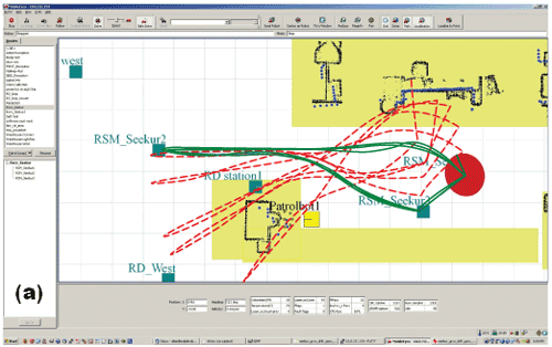
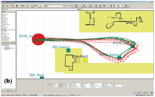
Fig. 6: A MEMS gyroscope can make a significant difference in robotic performance, as can be seen in the plot of Seekur path accuracy without MEMS gyroscope feedback (a) and with feedback enabled (b).
The difference in maintaining the path accuracy is easy to see when comparing the path traces in Fig. 6. It is important to note that these experiments were run on early generation MEMS technology that supported ~0.02°/s stability. Current gyroscopes enable two to four times performance improvement at the same cost, size, and power levels. As this trend continues, the ability to maintain accurate navigation on repetitive paths will keep improving, opening up additional markets and applications, such as specimen and supply delivery in hospitals.
Robot supply convoys
Current DARPA initiatives continue to call for more robot technology to help in force multiplication. Supply convoys are an example of this type of application, where military convoys are exposed to opposing threats while forced to move in slow, predictable patterns. Accurate navigation enables robots, like the Seekur, to take on more responsibility in supply convoys, reducing human exposure to threats along their paths.
One key performance metric, where the MEMS gyroscope heading feedback is particularly helpful, is in managing GPS outage conditions. The latest Seekur navigation effort, geared towards this environment, employs MEMS inertial measurement units (IMUs) for better accuracy and for their ability to incorporate future integration advances—for terrain management and other functional areas.
To test how well this system localizes — with and without the IMU — the error of an outdoor path was recorded and analyzed. Comparing the errors with respect to the true path (from the GPS) of the odometry only and those of the odometry and the IMU combined in the Kalman filter (Fig. 7 ) shows that positional accuracy is nearly 15 times better in the latter case.
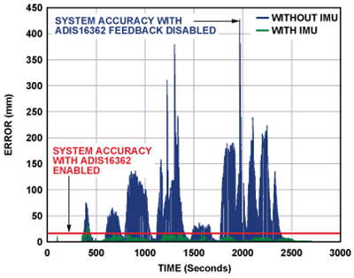
Fig. 7: Comparing Seekur position error using odometry only (blue) and using odometry/IMU (green) show the significant performance impact of the latter combination.
Future developments
Next-generation development for systems such as the Seekur could move from gyroscopes to fully integrated, 6-degrees-of-freedom (6DoF) MEMS sensors. While the yaw-oriented approach is useful, the world isn’t flat; many other applications, existing and future, can use integrated MEMS units for terrain management and for additional accuracy refinement. ■
Advertisement
Learn more about Analog Devices


