Optimizing the performance of a sensor system
Excitation and high-resolution measurement techniques with ADCs for transducer-based applications
BY ALBERT O’GRADY and MARY MCCARTHY
Analog Devices, Norwood, MA
http://analog.com
To maintain high resolution and accuracy within a transducer or sensor-based measurement system, the designer must exercise care in selecting the excitation source for the transducer — and the field-wiring scheme used in conveying the low-level analog signal from the transducer to the A/D converter. This article will focus on dc excitation methods applicable in sensor-based applications and on the measurement of low-level signals from the sensor using sigma-delta A/D converters with high resolution and accuracy.
Sensors and transducers are classified as either active or passive. Passive sensors, such as thermocouples, are two-port devices that directly transform physical energy to electrical energy, generating output signals without the need for an excitation source. Active sensors (like active circuits in general) require an external source of excitation. Typical resistor-based sensors, such as RTDs (resistance-temperature detectors) and strain gages require a current or voltage for excitation in order to produce an electrical output.
For a given excitation source, the system designer is faced with the challenge of measuring the output signal and dealing with the issues that may arise. For example, wiring resistance and noise pickup are among the biggest problems associated with sensor-based applications. A variety of measurement techniques are available for employment in quest of optimum performance from the measurement system. Principal choices include ratiometric vs. non-ratiometric operation, and 2-wire vs. 3- and 4-wire Kelvin force/sense connections.
Excitation and wiring techniques
Active transducers can be excited using a controlled current or voltage. In data-acquisition systems, it is not uncommon to see constant-voltage excitation used for strain and pressure sensors, while constant-current excitation is used to excite resistive sensors such as RTDs or thermistors. In noisy industrial environments, current excitation is generally preferable due to its better noise immunity.
Two major factors in selecting an excitation source will enhance overall system performance. First, resolution: the magnitude of the excitation should be sufficient for the minimum change in the variable being measured to produce an output from the transducer that is large enough to overcome the noise and offset in the system. Second, power level: if the sensor is resistive, the designer must ensure that the self-heating effects of the excitation current flowing through the transducer do not adversely affect the measured results.
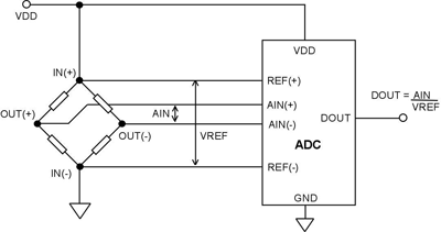
Fig. 1. Ratiometric operation in a bridge transducer application
Figure 1 shows a ratiometric configuration in a bridge-transducer application. The same reference source is used for both the transducer excitation and the A/D converter. A given percentage change in excitation is countered by the same percent change in the conversion process (or vice versa). The ADC output code, DOUT , is a digital representation of the ratio of the converter’s input, AIN , to its reference, VREF .
Since the input to the converter and its reference are derived from the same excitation source, changes in the excitation do not introduce measurement errors. Thus, in ratiometric configurations, if the variable being measured by the transducer is unchanged, the digital output code from the ADC is immune to variations in the bridge excitation. For this reason, an accurate stable reference is not necessary to achieve accurate measurements.
Ratiometric operation is very powerful; it permits measurement and control—using the system analog supply as a reference—to obtain accuracy independent of the stability of voltage references or excitation supplies. Because the power supply rejection of most ADCs is fairly high, drifts in the power supply voltage do not adversely affect the measurement.
Non-ratiometric circuits are principally suitable for applications requiring measurements against an absolute reference—or where a single converter serves a variety of unrelated analog inputs. Since changes in reference and excitation will not be removed but will be reflected in the measurement, highly accurate, precise, and stable references and excitation sources are required for most applications.
Figure 2 demonstrates the disadvantage of dc non-ratiometric operation. As in the previous application, the ADC outputs a digital code, DOUT , the ratio of AIN to VREF . In this example, however, the output code is sensitive to relative changes between the bridge excitation and reference voltage. Any change in the excitation voltage results in a change in the analog input voltage seen by the ADC. Since the reference is independent of the excitation, the digital output code will reflect the changed excitation.
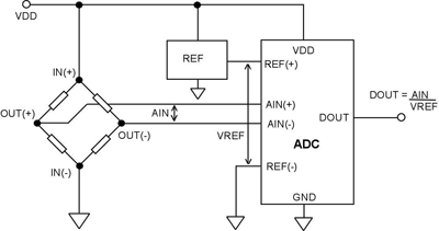
Fig. 2. Non-ratiometric operation in a bridge transducer application.
In the design of high-resolution data-acquisition systems, designers should always keep in mind the cost-effectiveness of ratiometric operation wherever its use is feasible.
A variety of wiring configurations can be employed when connecting to resistive sensors such as RTDs and thermistors in temperature-measurement applications. The basic 2-, 3- and 4- wire connections are shown in Fig. 3 .
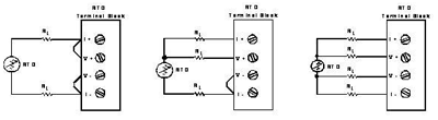
Fig. 3. Typical wiring configurations for resistive based sensors.
Why are these formats available, with their various complexities and costs? Lead-wire resistance can introduce significant measurement errors if adequate precautions are not taken to eliminate them, particularly in low-resistance 100-Ω RTD applications.
In RTD circuits, a controlled (usually constant) current is passed through the sensor, a resistor whose resistance increases gradually, repeatably, and approximately linearly with temperature. As its resistance increases, its voltage drop increases and, though small, can be measured without difficulty.
In an ideal application, the voltage measured should only include the increase in resistance of the sensor itself. In practice, though, especially in 2-wire configurations, the actual resistance between the sensor terminals at the point of measurement includes the resistances of both the sensor and the lead wires.
If the lead-wire resistance were to remain constant, it would not affect the temperature measurement. However, the wire resistance does change with temperature; and as the ambient conditions change, the wire resistance will also change, introducing errors.
If the sensor is remote and the wire is very long, this source of error will be significant in RTD applications, where the nominal sensor value is 100 Ω or 1 kΩ, and incremental changes are on the order of 0.4%/°C. Thermistor applications, where nominal sensor resistance values are higher than those of RTDs, tend to be less sensitive to lead-resistance, since the leads contribute less error.
The 2-wire configuration is the least accurate of the three systems shown above, because the lead wire resistance, 2RL, and its variation with temperature contribute significant measurement errors. For example, if the lead resistance is 0.5 Ω in each wire, RL adds a 1-Ω error to the resistance measurement. Using a 100-Ω RTD with α = 0.00385/°C, the resistance represents an initial error of 1 Ω/(0.385 Ω/°C) or 2.6°C; variation of the lead resistance with ambient temperature contributes further errors.
The 3-wire configuration in Fig. 3 offers significant improvements over the 2-wire configuration due to the elimination of one current-carrying lead wire. If the measurement wire returning to V(+) feeds into a high-impedance node, no current flows in this wire and no wiring error is introduced. However, the lead resistance and thermal characteristics of the RTD return wire to V(–) and I(–) still introduce errors, so the errors have been reduced to one-half that of a 2-wire system.
The 4-wire configuration in Fig. 3 offers the best performance, in terms of accuracy and simplicity, compared to the 2- and 3- wire configurations. In this application, the errors due to the lead-wire resistance and thermal heating effects are removed by measuring the temperature right at the RTD. The return wires from the RTD are generally buffered by a high-impedance circuit (amplifier/analog-to-digital converter), and thus no current flows in the return wires and no error is introduced.
Example of ratiometric configuration with voltage excitation
A weigh-scale system is shown in Fig. 4 . In the system shown, a dc voltage is used to excite the loadcell. The magnitude of the excitation voltage needs to be sufficiently high and the ADC needs to have good performance so that the signal from the load cell is larger than the peak-to-peak noise of the ADC. For example, ADI’s AD7190 24-bit sigma-delta ADC can accept reference voltages as high as its analog power supply. Therefore, the excitation voltage for the load cell can be as large as the ADC’s analog power supply. This voltage can also be used as the reference to the ADC. The device also accepts a differential reference and a differential analog input, so it is easy to obtain a ratiometric configuration. Any change in the excitation voltage will not affect the accuracy of the conversions. The ADC also contains a PGA, so the only external components required are some filters for EMC purposes.
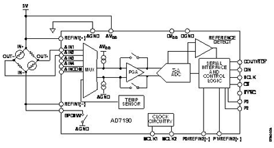
Fig. 4. Ratiometric weighscale measurement system.
Load cells can be 4-wire or 6-wire. As with RTDs, the device with the higher number of inputs gives better accuracy. A 6-wire load cell (shown in Figure 4 ) has two sense pins in addition to the excitation/ground connections and the output connections. These sense pins are connected to the high side and low side of the Wheatstone bridge so, the voltage developed across the bridge can be accurately measured and used as the reference to the ADC.
Therefore, a ratiometric configuration is used to design the weigh scale system. With this configuration, the system is immune to low-frequency changes in the excitation voltage. With a 4-wire load cell, the sense pins are not present, so the ADC reference pins are connected to the excitation voltage and ground.
With this arrangement, the system is not completely ratiometric as there will be a voltage drop between the excitation voltage and SENSE+ due to wire resistance. There will also be a voltage drop due to wire resistance on the low side.
Therefore, using a ratiometric configuration in addition to a 6-wire loadcell optimizes the system.
Example of ratiometric configuration with current excitation
RTD
RTDs typically use current excitation. As previously discussed, a 4-wire RTD gives the best performance as the lead resistance does not introduce system errors. Figure 5 shows how a 3-wire RTD can be configured to minimize the lead resistance errors. RL1, RL2, and RL3 are the resistances of the RTD’s leads.
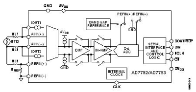
Fig. 5. Active RTD Sensor Measurement System
To fully optimize a 3-wire RTD configuration, two identically matched current sources are required. In this 3-wire configuration, the lead resistances cause errors if only one current source (IOUT1 ) is used because the excitation current flows through RL1 , developing a voltage error between AIN1(+) and AIN1(–) .
The second RTD current source (IOUT2 ) is used to compensate for the error introduced by the excitation current flowing through RL1. The absolute accuracy of each current source is not important, but good matching of the two current sources is essential. The second RTD current flows through RL2 . Assuming RL1 and RL2 are equal (the leads are normally of the same material and of equal length), and IOUT1 and IOUT2 match, the error voltage across RL2 cancels the error voltage across RL1 , and no error voltage is developed between AIN1(+) and AIN1(−) . Twice the voltage is developed across RL3 , but this is a common-mode voltage, so it does not introduce errors.
Here 16-/24-bit sigma-delta ADCs, such as AD7792 and AD7793, have two matched excitation currents on-chip to simplify the design of the RTD system. The part has differential analog inputs and accepts a differential reference, allowing a ratiometric configuration to be implemented. In Fig. 5, the reference voltage for the ADC is also generated using the matched current sources.
This reference voltage is developed across the precision resistor, RREF , and is applied to the differential reference inputs of the ADC. This scheme ensures that the analog input voltage span remains ratiometric to the reference voltage. Any errors in the analog input voltage due to the temperature drift of the RTD current source are compensated by the variation in the reference voltage.
Thermocouple
Figure 6 shows a thermocouple system. Measuring the voltage generated by the thermocouple does not require a ratiometric configuration. The voltage generated by the thermocouple is an absolute measurement, so a good reference source is required. However, for the cold junction compensation, a ratiometric configuration may be used. A thermistor is used to measure the cold junction temperature.
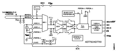
Fig. 6. Passive thermocouple sensor measurement system.
A single current source is normally used with a thermistor. The thermistor resistance is large compared with the resistance of the leads. Therefore, lead resistance does not affect the accuracy by a significant amount.
As with the RTD, using a precision resistor for the reference, with a current source driving the precision reference resistor along with the thermistor means that a ratiometric configuration is achieved. This means that the accuracy of the current source is not important, as drift of the current source affects both the thermistor and reference resistor, thus canceling its effect. ■
Advertisement
Learn more about Analog Devices


