Selecting the right device depends on voltage, not semantics
What is the difference between an Optocoupler vs. Optoisolator?
Industrial terminology often blurs the lines between similar terms. Today we find that both the terms optocoupler and optoisolator are used interchangeably to refer to the same function. The distinguishing feature between these two terms is the amount of voltage being isolated. An optocoupler is used to transmit either analog or digital information from one voltage potential to another while maintaining isolation of the potentials of less than 5,000 V. The optoisolator is designed to isolate power systems while transmitting analog or digital data between the systems with isolation voltage between the power systems from 5,000 to more than 50,000 V.
How they operate
Both optocouplers and optoisolators allow the transfer of signals and data from one system to another within a piece of electronic equipment without a direct electrical connection. This is done optically by using a beam of light to an optical receiver in a single package with a light-conducting medium between the emitter and detector. This allows the total electrical isolation of electronic circuits while transmitting information from one voltage potential to another. In all optocouplers and optoisolators, input signals are converted to a pulse of light from an LED. This pulse of light is transmitted to a silicon photosensor.

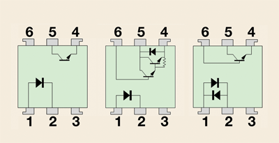
Optocoupler configurations can vary depending on the application.
Design considerations
The photosensor can be either analog or digital depending on the type of input signal to be transferred across the device. When an application requires an analog signal, such as for 4 to 20 mA, the photosensor can be either a photodiode or phototransistor. Both of these devices provide an analog output signal that can be used for a variety of analog applications.
An analog response is required for those applications where the amount of signal is critical to the operation of the system. The amount of current on the output of the device referenced to the amount of light into the LED is called the current transfer ratio (CTR), the output current divided by the input current. CTR values may vary from 10% to over 5,000%, depending on the gain of the system. Typically the lower the CTR, the faster the rise and fall times.
Analog devices normally require additional circuitry to be utilized by other components of the system. Digital output devices are best suited when the application requires a pulse, or bit output.
These devices are most often easier to use while providing a reliable signal that can interface directly with other system components. As long as sufficient light is shining on the photosensor, the output signal will be either high or low depending on the logic configuration.
A consideration facing designers is the speed of transmitting the digital data while minimizing the propagation delay. Most optoisolators/optocouplers are used for data rates below 10 Mbits/s, and the propagation delay may be in the 2 to 20-µs range.
The optocoupler
Optocouplers are specifically designed as small package devices similar to a Dual In-Line Package (DIP) or a surface-mount device (SMD), so that they take up the least amount of space while using light to transmit the data. The designer should pay attention to the definition of the isolation voltage potential because it may be identified as an ac, rms, or dc value.
The optoisolator
Optoisolators are available in a multitude of package styles including rectangles, cylinders, and specialty configurations. These package types are designed to provide higher isolation voltages than what can be achieved with DIP and SMD packages.
While using the optoisolator, the designer may need to take into consideration the environmental conditions. For example, percentage of humidity in the environment would be a key consideration if the system requires 50,000 V of dc isolation.
If the humidity in the air is too high, an arc may occur around the optoisolator or along the surface of the PCB, resulting in a conductive path and shorting around the device. Distance, temperature, barometric pressure, type, and amount of contaminate in the air, as well as humidity, define the breakdown potential exterior to the optoisolator.
Device configurations
Optocouplers and optoisolators are available with a single LED or back-to-back LEDs (anodes and cathodes are tied together). The configurations for the optical sensor may vary from a single photosensor to a fully integrated receiver. ■
BY BOB PROCSAL
OPTEK Technology
Carrollton, TX
http://www.optekinc.com
Related articles:
Advertisement
Learn more about TT electronics Optoelectronics Business Unit (OPTEK)


