BY VARUN MERCHANT
Mainstream Technical Marketing Manager
Tektronix
www.tek.com
Regulatory institutions all over the world have started noticing the problem of creeping standby power for electronic products that plug into a wall socket. Committees like the International Electrotechnical Commission (IEC) have taken active steps to publish standards, such as IEC62301, that specify standby power limits for home appliances. Similar standards or derivations thereof are implemented in various regions around the world.
Traditionally, tests for compliance to such standards are performed at the end of the design cycle, but the situation changes quickly if the design fails compliance testing — board turns and re-testing can get expensive and time consuming. Avoiding such scenarios points to the need for pre-compliance testing earlier in the design cycle.
Standby power measurement challenges
Looking at an example of low standby power on the input side of a power supply recorded over time (Fig. 1 ), it becomes immediately apparent that the power is quite distorted, peaky, and irregular. It’s also very low. For instance, if you were measuring 10 mW of standby power in Europe with 230-V input, your current could be as low as 40 µA. For 5 mW, the current goes as low as 20 µA.
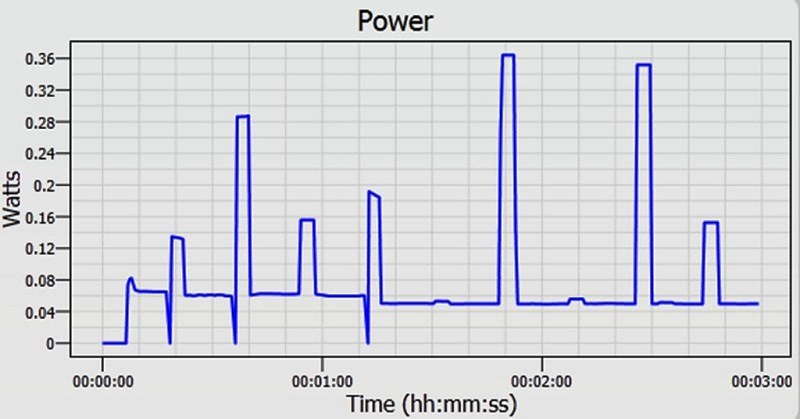
Fig. 1: Low standby power measurements are often peaky and irregular.
Low current leads to a number of problems. Waveforms are highly distorted because power supplies operating at low loads often draw non-sinusoidal, very high-crest-factor current. The power factor is low because the current may be predominantly capacitive through the power supply’s EMC filter. The power draw may also be irregular if the power supply is in a burst, or hiccup, mode to minimize input power.
The crest factor, which is simply the peak value divided by the rms value, is often very high when measuring stand- by power. To understand why, consider the front-end stage of a typical ac-dc power converter (Fig. 2 ). In most cases, the input rectifier is followed by a by-pass capacitor designed to smooth out the input voltage ripple and provide a fairly stable dc for the next conversion stage. The input current flows only when the bypass capacitor voltage is lower than the input ac voltage peak. The amount and timing of current flowing into the circuit is dependent upon the capacitor value and total load current. This leads to narrow and peaky currents on the input side. PFC circuits can be designed to mitigate this effect at full load, but unfortunately, most PFC circuits are not active at no-load.
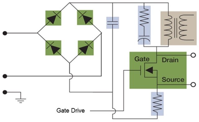
Fig. 2: In the front-end stage of a typical ac-dc power converter, the capacitor plays a key role in determining crest factor.
When dealing with such signals, another important issue to keep in mind is the power factor. Traditionally, power factor is defined as: PF = cos Φ, where Φ is the angular difference between the peak voltage and current. In cases like this, the non-sinusoidal current is in line with the voltage, but VA — the voltage-current product, or apparent power — is much higher than the actual active watts, or real power. This means that, for all practical purposes, power factor should be defined as:
PF = Real power (in W)
Apparent power (in VA)
IEC 62301 testing
The latest IEC 62301 Edition 2 standard for standby power recognizes the challenges involved with testing standby power, taking them into consideration and recommending test methods.
The wall socket voltage quality in most labs is likely not great and, in most cases, could lead to failing the IEC stand- by power tests due to voltage harmonic content or out-of-limit crest factors. It is, therefore, highly advisable to use an ac source with defined tolerances, even for pre-compliance testing. The voltage source should be within 1% on voltage and frequency output and below 2% on total harmonic content up to 13th order. Voltage crest factor should be within 1.34 and 1.49.
Measurement uncertainty is based on both the level of power to be measured and the distortion and phase shift of the waveform. To take into account both distortion and phase shift, maximum current ratio, or MCR, is defined by IEC 62301 as:
MCR = Crest factor
Power factor
The required level of uncertainty is determined using a flow chart provided in the standard. This defines the minimum accuracy and noise levels required for measurement equipment. The required accuracy for a power analyzer is about 2% at 1 mW and 4% at 0.5 W. Some standards, such as Energy Star, are more demanding, with a 2% accuracy requirement at 0.5 W. This means that your power analyzer should have a minimum watt accuracy of 2% or better with a resolution of 10 mW or better. It should be noted that, because there is so much variability, the uncertainty needs to be calculated in real time while the test is running and then included in reporting.
Both direct meter reading and average reading test methods are effectively obsolete, with the latest specification calling for a sampling test method. Stability of measurements is determined from a least-squared linear regression through all of the power measurements. Stability is established when the slope of the straight-line regression is either less than 10 mW/h (input power ≤ 1 W) or less than 1% of the power if the power is greater than 1 W.
Test setup is critical for low power measurements. In a typical setup using a power analyzer (Fig. 3 ), a breakout box helps to make connections safe and easy by providing two terminals to switch between source and load side.
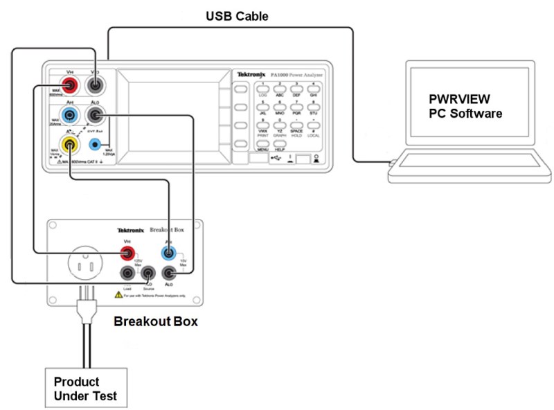
Fig. 3: In this IEC 62301 test setup using a Tektronix PA1000 or PA3000 power analyzer, having a breakout box is very beneficial — and safe!
There are two ways to connect the voltage and current channels for measuring power. One way is when the voltage measurement across the load is more accurate than the current, and the other way is when the current across the load is more accurate than the voltage. The connection choice depends on whether the load current is very low or if the power draw across the voltage channel impedance will be a significant part of the total power measured. By moving the current measurement to the load side, the current flowing through the voltage channel is ignored (Fig. 4, right ).
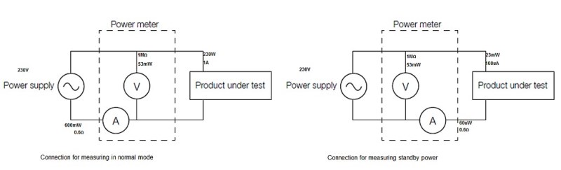
Fig. 4: Proper connections are critical for low power measurements.
On the other hand, if the load current is higher, the power dissipated across the physical shunt can be high enough to generate an error in power readings. To prevent this, power analyzer current shunts are set up so that a drop across it is ignored by moving it toward the source side (Fig. 4, left ). In the case of a test setup with a Tektronix PA1000 or PA3000 power analyzer (Fig. 3 ), the impedance across the voltage channel is 1 MΩ, and the impedance across the 1-A current shunt is 600 mΩ. Although these values can vary for different power measurement devices, most are very similar.
Taking the impedance numbers into consideration, the drop across a voltmeter channel would be 53 mW when supplied from 230 V. This is not a significant number when measuring power in hundreds of watts, but when the power is as low as 30 mW, this can lead to a very substantial error.
Similarly, the power draw across a shunt with a 100-uA current is just 60 uW. But with a 1-A current, the drop can be as high as 600 mW. Such drops across measurement channels can significantly influence readings and generate wrong results. Consequently, care should be taken in making connections, especially while measuring very low power values. Again, a breakout box helps by providing two different terminals for switching between source and load sides.

About the author
As Mainstream Technical Marketing Manager for Tektronix, Varun Merchant supports mid-range wireless and power conversion product offerings. Before joining Tektronix, he worked for several years in product development and design in the semiconductor industry. He holds an MSEE from the University of California, Santa Barbara and an MBA from the Stern School of Business, NYU.
Advertisement
Learn more about Tektronix


