Overcoming the design challenges using HB LEDs
When using these parts in portable products, designers must consider some important parameters
BY JOSE RODRIGUEZ
Analog Devices, Norwood, MA
http://www.analog.com
Flash LED lighting in handsets has become an important aspect of the end-user experience, allowing the capture of images in low-lighting conditions. The need for assist lighting has also increased due to the use of higher-megapixel cameras, which tend to have lower performance in low-light conditions due to their higher pixel densities and smaller pixel size.
In order to provide a high-quality image with the flash LED, it is important to take into account certain system parameters that can affect the LED performance. In this article, we will discuss some important parameters that need to be considered when designing with high-brightness LEDs in portable systems such as LED specifications, battery currents, layout, and thermal considerations.
Light output
When choosing the LED, the designer must consider several parameters. One of the first requirements that must be met is light output (measured in lux) at 1-m distance and flash timing. Image sensor suppliers often provide specifications as to the minimum requirements for their sensors in low-light conditions. This requirement can be used as the first step in determining which LED to use and the current required by looking at the LED luminous intensity at 1 m versus current specification, typically provided by the LED manufacturer.
New-generation LEDs and drivers can achieve up to 300 lux at 1 m with 1.5-A peak pulse drive with a single LED. This level of performance typically provides enough light output with a single LED for the high-end megapixel cameras commonly used in today’s handsets without requiring the extra cost of two LED systems.
An advantage of LED lighting over xenon is the ability to provide assist lighting in low-lighting conditions for video capture, autofocus, and viewfinder light prior to taking a picture, while xenon can only be used for the flash itself. Newer-generation LEDs can handle up to 500-mA dc currents for use in assist lighting although, typically lower levels are used in the 100 to 200-mA range for handsets.
The LED color is another parameter that must be considered when selecting the LED parameters. The flash LED color can affect the colors of the captured image, so it is important to choose a chromaticity in the pure-white range for best image results. Some LED suppliers provide binning options to reduce the chromaticity color variations.
Battery current
The current through the battery over operating conditions must be taken into consideration when choosing LED current and light output. In addition, portable Li-ion batteries typically contain short-circuit protection to protect the battery during conditions of large-current discharges.
The short-circuit protection may vary depending on the supplier of the battery and the designer’s requirements. The scenario of most concern occurs when the battery is operating at lower operating voltages. Since the LED VF can be higher than the battery during lower-voltage conditions, the LED driver must boost the voltage provided to the LED for the LED to turn on at the programmed current.
Since the voltage is boosted, the supply current to the driver will be higher than the current through the LED. The increase in current will be based on the boosting factor and driver efficiency. For example, an LED drive current of 1 A can require up to 1.5 A out of the battery at nominal battery conditions of 3.5 V and typical efficiencies.

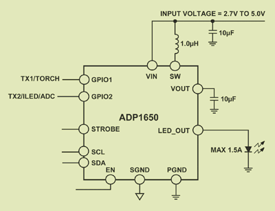
Fig. 1. Flash LED driver with current source driver.
Another critical specification in this case is the flash-output current tolerance. The variation in the output current will not only potentially impact the picture quality, but also the load variation in the battery current. Therefore, having a high-efficiency LED driver with tight tolerances on the output pulls less current from the battery for a particular LED current and light output.
RF TX current
The RF transmitter currents must also be considered when it comes to the battery specification. The combination of the RF power amplifier (PA) transmission load and LED flash currents can lead to the handset exceeding the battery specifications. RF transmissions are typically controlled at lower layers in the baseband software, and they can happen regularly during normal background communications between the handset and base stations.
Since these background tasks typically happen at different software layers than the camera control software, it becomes difficult to eliminate these from happening at the same time. Some LED drivers have the ability to reduce the current of the flash LED during RF transmissions, by using a pin to enable a reduced current mode typically referred to as “transmitter mask” (TxMask) in the industry.
Having this software programmability of the flash LED currents during an RF transmission allows the user to reduce the flash current without affecting the handset operation. LED drivers that have status indication of a reduction in flash LED light output due to a transmission provide designers with the information necessary for making adjustments. With this knowledge, the software can perform a quick second flash and image capture to reduce the chances of overlapping a transmission or can perform an image adjustment.
Battery ESR
In conjunction with the system current, the battery ESR (equivalent series resistance) plays a critical role in determining the minimum operating voltage for the battery. Some battery ESR specifications can vary from 100 to 200 mΩ over the life of the battery. A 1.5-A current out of the battery would be equivalent to a 150 to 300-mV voltage drop through the battery ESR, which could make the operating voltage of the portable device drop below minimum operating conditions at low-battery conditions.
Operating below the minimum operating voltage can affect critical circuits in the handset. A reduction in flash currents may be necessary to extend the operating range of the flash, so programmability of the LED driver and tolerances can play a critical role in the flexibility offered to the designer.

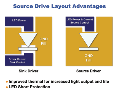
Fig. 2. Sink driver vs. source driver.
Temperatures
Thermal considerations in high-current LED designs are important from an LED life and performance as well as protection considerations. High temperatures on the LEDs can lead to premature field failures, and LEDs can lose between 15% and 20% of luminous intensity when operating at high temperatures. It is very important that proper layout considerations are taken into account for providing protection and proper heat dissipation to the LED. This is an area where the driver technology can help improve the PCB layout.
Using an LED driver with a source driver to the anode of the LED allows the cathode of the LED to be grounded (see Fig. 1 ). Such a source driver architecture offers inherent protection against short circuits on the LED as well as a connection to the ground plane for heat dissipation (see Fig. 2 ).
The connection to the ground plane offers better shielding and a direct return of the LED currents to the battery ground, whereas sink drivers require a return to the LED driver and then ground. Other thermal protection features that are necessary for flash LED drivers are flash LED max timeouts to prevent driving LEDs at high currents for extended times and die temperature monitoring.
Other considerations
Once the design requirements and constraints have been analyzed such as light output, current capabilities, and minimum operating voltage of the system, the designer can then choose an LED driver that meets all of the design criteria. High-current LED drivers such as the Analog Devices ADP1650 can provide the basic architecture, hardware and software features needed to address the system design requirements of high-current-LED flash designs. ■
Advertisement
Learn more about Analog Devices


