Picking an electronic load for power source testing
Choosing the right load requires understanding both the UUT’s test needs and the candidate loads’ capabilities
By MARTIN O’DONNELL
Chroma Systems Solutions
Irvine, CA
http://www.chromausa.com
Having been around since the early 1960s, electronic loads evolved out of the need to emulate real world applications in testing power supplies as well as batteries, and now fuel cells. The first electronic loads used bipolar transistors and have now settled on utilizing FET technology to better dissipate the power in the form of heat. Getting the most out of the latest loads requires that users first consider the test approach their UUT requires, and then understand what loads can do their needs.
Getting started
When selecting a load that best fits an application, the first and most important task is to understand the unit under test (UUT) and how it needs to be tested. Specific questions may include:
What are the lowest voltage/highest current operating points? (Cable drop should be considered.)
What specific measurements are needed? (RMS measurements; digitize V and I, etc.)
Will one or many UUTs be checked simultaneously? (If many, true master/slave capability is critical.)
Are highly accurate loads at both low- and high-current settings needed? (If so, three current ranges are necessary.)
Are minimizing cable drops and series inductance critical? (Front-panel connections are then needed for accurate loading.)
Is a system that can be reconfigured quickly for changing applications needed? (Front-panel modularity is critical to maintainability and configuration.)
Answering these questions will ensure that, when the product is placed in the field, its quality and reliability meets required standards. Testing considerations also include output regulation, noise measurements, high-line and low-line ac, transient measurement, and protection circuit operation.
Load selection
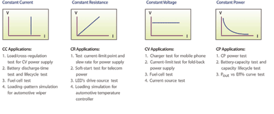
Once it is decided which tests are required, a load may be selected. The four main modes of operation for an electronic load are constant current (CC), constant resistance (CR), constant voltage (CV), and constant power (CP) (see Fig. 1 ). Most manufacturers also include specialty modes for unique testing requirements, but remember: no matter what mode the electronic load is in, it is always controlling the current.

Fig. 1. To deliver the types of operation modes shown, loads must precisely control current.
CC mode allows the test engineer to set a current level that the load will draw regardless of any change in voltage. CR mode allows the test engineer to set a resistance value and the load will adjust the current draw inversely in accordance with Ohm’s Law (R = V/I) to compensate for any change in voltage in an attempt to keep the “resistance” value at a constant.
CV mode allows the test engineer to set a voltage that he wants to remain constant and the load will sink the necessary current in an attempt to keep the voltage at the set level. CP mode allows the test engineer to set a wattage level that the test requires and will adjust the current draw proportionately to compensate for any change in voltage (P = IV). This will all hold true unless something occurs, triggering one of the protection modes.
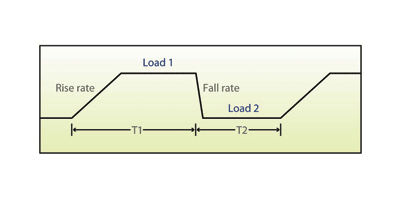
Specialty features such as dynamic loading, load profiling, constant impedance, short circuit, and low voltage operation may be required for unique load emulation. Dynamic loading includes the ability to pulse load the power supply in an attempt emulate the actual load. In dynamic loading, the parameters of your load profile may be manipulated so as to get as close as possible to the actual load profile of the device the power supply will be powering (see Fig. 2 ). Adjustable parameters may include slew rate, frequency, duty cycle, baseline current, amplitude, and triple step values.

Fig. 2. The ability to manipulate load parameters such as slew rate, duty cycle, and more can simulate the required load profile.
Beyond square waves
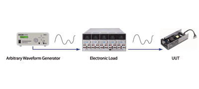
The limitation of most dynamic load profile schemes is the inability to generate anything other than a square wave. If the UUT requires a load profile that is more than an on/off, square wave type, then the load chosen will need to include a 0 to 10-V analog input, which allows the test engineer to input an analog representation of his waveform at the external modulation input. The load will then track this input and adjust the current draw to the corresponding value (see Fig. 3 ).

Fig. 3. An arbitrary waveform generator used with a load permits creation of complex load profiles.
For example, the full scale of the load selected is 300 A and the external modulation’s input is rated for 0 to 10 V. The 0 to 10-V waveform put across this input will have a resolution of 30 A/V. For both dynamic loading and load profiling, the load should have a bandwidth between 10 and 20 kHz.
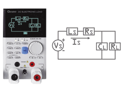
Some power supplies react differently on initial turn on when impedance resistance, capacitance, and/or inductance — is present. This cannot be effectively emulated by any of the four current modes of operation. A newly developed capability, recently made available in 63600 series modular loads, is constant impedance (CZ). This mode provides the ability to simulate the impedance of the actual load during current changes and startup. CZ mode lets test engineers set up the electronic load with the values of capacitance, inductance, and resistance of the actual load to test for real-world transients (see Fig. 4 ).

Fig. 4. A load with a constant-impedance mode lets users test supply performance for real-world transients.
The short-circuit function will test the UUT’s current limit function by driving it to beyond its maximum current rating. Measurement can be made in both the current limit operation and the current trip level.
Most electronic loads cannot provide full scale current draw at very low voltages. Typically FET loads can provide maximum current draw at 1% of the rated voltage. For example, if the load’s full-scale voltage is 100 V and its full-scale current is 100 A, it typically can provide 100 A of current draw down to 1 V (1% of FS). As the voltage potential across the load is reduced below 1 V, the current draw will be reduced exponentially all the way down to 0 V. Keep in mind that this is the voltage potential at the load, not at your UUT. While ultra low voltage testing is more common in fuel-cell and battery testing, it may still be required for certain power supply or dc-to-dc converter apps.
Load cooling and protection
The two cooling methods available are air and water. The air-cooled loads tend to be more robust and easier built; however, the air-cooled loads are more expensive than the water-cooled. One key issue regarding the cost of water-cooled loads that is frequently overlooked is the cost of the chiller or chilling system. Typically the cost differential is negligible until you reach about 30 kW, unless of course your facility already has chilled water.
Air-cooled loads are portable and can be shared between departments if needed, while water-cooled loads are tied to a cooling system and cannot be moved without altering the plumbing. At many companies, installing water-cooling also involves the intervention of the facility manager.
Condensation is a design problem that has not been completely eliminated from water-cooled systems. Many water-cooled load failures are attributed to condensation forming on the components and shorting out the power section. This type of failure can be catastrophic leaving your load irreparable. Water control valves and water servo’s attempt to prevent the chilled water from flowing when the load is not hot; however, these designs aren’t fool proof.
Protection features are essential to protect not only the electronic load, but also the power supply/UUT. Protection features may include over current (OC), over voltage (OV), over power (OP), over temperature (OT), under voltage (UV), oscillation control, and reverse-current protection (RCP).
System solutions
Many test engineers utilize complete systems for their power supply testing requirements. Such systems (the Chroma C8000 is an example) provide a comprehensive way to emulate the real world applications and collect essential data.
These systems include a wide range of hardware such as oscilloscopes, ac and dc sources, electronic loads, power meters, noise analyzers, and DMM’s. Married with flexible software, the hardware can provide for years of testing, which will grow with the user’s product line. These systems can be utilized both for design evaluation and go/no go testing, which allows R&D and manufacturing to coordinate their efforts via common test equipment. ■
Advertisement
Learn more about Chroma Systems Solutions


