Pin-fin heat sinks:
A cool alternative
Pin-fin heat sinks offer designers a
space-efficient cooling solution
BY BARRY DAGAN
Cool Innovations
Concord, Ontario, Canada
http://www.coolinnovations.comAs dissipated heat loads continue to rise, engineers seek increasingly efficient heat sinks. The efficiency of various heat sink technologies can be measured by the space they occupy in relation to the thermal resistance they provide. Because of their efficient pin-fin structure and use of highly thermally conductive materials, pin-fin heat sinks can provide highly efficient cooling solutions, that is, with very high volumetric efficiencies. Volumetric efficiency is the product of a heat sink's thermal resistance and its physical volume. The large surface area, omnidirectional pin configuration, and round nature of the pins in pin-fin heat sinks enable them to dissipate very high thermal loads per volume. With footprints ranging from 0.35 x 0.35 in. to 7.0 x 7.0 in. and heights between 0.15 and 1.7 in., pin fins can be used to cool surface-mount components, board-level components, power modules, CPUs, and other devices. Pin fins for power modules Because power modules dissipate high heat loads, pin fins for power modules should possess dense pin arrays designed to maximize the heat sink's surface area. Pin fins with dense pin configurations are most effective in the impingement-cooling mode, where a fan is placed above the heat sink and air is blown directly down on to the pins. Forced air creates significant turbulence between the pins and enhances their cooling abilities.

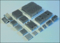
Available in a wide range of sizes, pin-fin heat sinks offer a space-saving cooling solution.
Compared to the traditional horizontal cooling mode, impingement cooling improves performance by approximately 20%. Impingement cooling also distributes airflow evenly along the surface of the heat sink. As a result, the temperature gradient that is typical to forced horizontal cooling is eliminated and the “hot end” of the heat sink is avoided. For instance, a 672-pin heat sink with a footprint of 5.0 x 5.0 in., a thermal resistance of 0.08°C/W, and an overall height of 1.7 in. dissipates 500 W over a 40° temperature rise. Surface-mount components With the exception of CPUs that operate in the impingement-cooling mode, most surface-mount components are cooled using central-air sources, exposing board-level devices to different airflow amounts. Components that are adjacent to air sources are typically exposed to significantly higher airspeeds than those further away from the application's air sources. By controlling pin density, pin-fin heat sinks can be designed to operate efficiently with different air velocities. With high airspeed, a dense pin configuration is appropriate, as the powerful airflow is able to push through the pins. With low airspeed, a low pin density is suitable because the airflow is not strong enough to penetrate a dense pin array. As an illustration, a 64-pin pin-fin heat sink with a 1.5 x 1.5-in. footprint, an overall height of 1.1 in., and a surrounding airspeed of 400 lfm dissipates 5 W within a temperature rise of 5°. The heat sink's thermal resistance is 1.04°C/W. Using computational fluid dynamics analysis tools, engineers can design optimal pin configurations for their own applications. Pin fins for CPUs The increased processing power generated by today's CPUs has been accompanied by a sharp increase in power dissipation. At the same time, today's modern applications demand compact packaging and increased reliability. Pin-fin heat sinks for CPUs can provide excellent cooling solutions. As an illustration, a pin fin with a footprint of 2.5 x 2.5 in. and a height of 1.7 in., operating in the impingement-cooling mode, provides a thermal resistance of 0.37°C/W.
Advertisement


