BY PATRICK LE FÈVRE
Marketing and Communication Director
Ericsson Power Modules
www.ericsson.com
Uptime and energy efficiency are now the two most important factors in the design of infrastructure equipment such as compute servers and network switches and gateways. The key to both is understanding in real time, what is happening inside the system.
Today’s infrastructure equipment comprises multiple blades, often with multiple system-on-chip (SoC) and field-programmable gate array (FPGA) devices on each. The distributed power architecture common to these systems allows fine-grained power control for each, often with support for hot swap to allow failed components to be switched out and replaced without affecting the rest of the system. Ensuring that the power delivered to each blade and processor is within tolerance and at the appropriate levels demands the ability for the system controller to understand what is going on. A key component of that architecture is the Power Management Bus (PMBus).
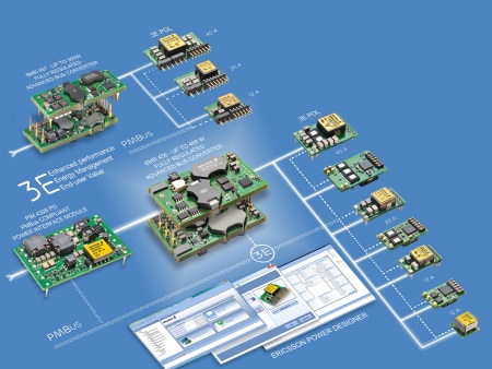
Ericsson power module family
First published as a standard in March 2005, the PMBus is an open protocol for power management that uses commands and responses sent over a serial bus to coordinate the power converters within system with a host controller. PMBus is designed to make it possible to manage individual PoL converters on each blade or board within the system, providing fine-grained control over power.
Using PMBus, the system controller can ensure that power is sequenced properly to avoid disruption to the main power bus if too many loads are introduced after a board has been inserted. The PMBus provides commands to shut down power converters automatically ready for a hotswap event and it provides vital monitoring and control functions to ensure that the power converters are working as expected and are not suffering from faults.
The latest release, version 1.3, increases the granularity of control with increases to protocol data-rate, data resolution and the addition of a protocol to support the increasingly important feedback loop between point-of-load (PoL) converters and their loads (see PMbus_ConnectionsGraph).
The PMBus is derived from the System Management Bus (SMBus), providing the two signal lines supported by I2C on which SMBus is based as well as an additional alert line used that allows any node on the bus to interrupt the system master. This reduces the need for that master to continuously poll slaves for updates.
Although geared for simplicity through the use of one-byte command codes, PMBus supports more than 100 power-management commands, which still leaves considerable room for expansion. The standard also allows for two-byte commands to be used in the future. Typical commands are used to set the output voltage of a PoL converter and to set the thresholds for warnings and faults as well as control voltage margining to help support system test.
Voltage margining can be used during test to determine whether IC performance will suffer excessively due to minor variations in supply voltage. Any marginal or out-of-specification devices can be detected during this process and replaced before leaving the production facility, reducing the probability of an expensive failure in the field.
Historically, margin testing was difficult to perform, often demanding the temporary fitting of resistors to dc/dc converters to force their output voltage to vary outside the nominal range. The voltage-margining commands with PMBus allow the tests to be performed automatically, through a pair of commands that can force the voltage either higher or lower. Version 1.3 of the PMBus standard introduces the ability to support relative voltage threshold settings as well as absolute so that they scale with changes in the output voltage, easing the creation of test and maintenance firmware.
PMBus version 1.3 goes further in its ability to fine-tune voltage control through the addition support for adaptive voltage scaling (AVS). The introduction of AVS recognizes the requirement for dynamic voltage control among the latest generations of ASICs, FPGAs and microprocessors. To optimize their power consumption as performance requirements change in real time, these devices demand subtle changes to the voltage supplied by the PoL converter. Processor manufacturers have developed proprietary protocols to allow these needs to be communicated to power converters, but each needs specific support. Implemented as a simple extension to PMBus, AVS provides a standardized protocol for these devices to communicate their needs to the converter (see Fig. 1 ).
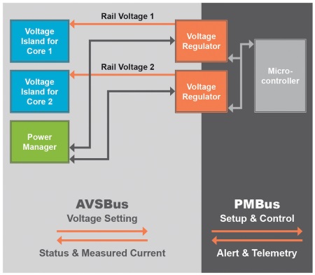
Fig. 1: AVSBus uses a simple extension to PMBus to communicate with the power converter.
To ensure accurate power delivery, AVS supports the ability for the PoL converter to detect the voltage and current supplied to the device, allowing the implementation of closed-loop control algorithms to ensure the supply rails remain within tolerance.
Rather than being based on the I2C bus as the PMBus itself is, the AVSBus resembles an SPI serial bus. But as it is a point-to-point connection, it dispenses with the chip select (CS) line. The result is a three-wire connection with one clock and two data lines (see Fig. 2 ). Connection via PMBus through the PoL converter allows the status of the AVS-controlled subsystem. AVS returns status data with each transaction indicating either an alert, such as an over-current situation or other malfunction, or a successfully completed voltage change.
Fig. 2: AVSBus also resembles SPI serial bus but only has a 3-wire connection
One of the issues with earlier forms of the PMBus is the need to successively poll slaves if an error condition arises. Version 1.3 of PMBus introduces a feature that takes advantage of the structure of I2 C to accelerate the time it takes to diagnose a failure or problem. The Global Process Call creates a broadcast request using one of the PMBus' reserved addresses (see Fig. 3 ).
Fig. 3: Version 1.3 speeds up the time to diagnose a failure compared to earlier versions of PMBus
Every slave that understands the command is expected to reply. Through the open-drain structure of PMBus, the protocol is able to use bit-dominant arbitration to determine which slave has sent the highest value and thus the most serious condition corresponding to the request. The system controller can then interrogate the slave that has the highest-priority condition or build a list of slaves that need attention by repeating the command. Each slave that lost the previous round will reply again until all slaves have been dealt with.
Other commands based similar uses of the Global Process Call make it possible to also determine other data such as the slave passing the highest current or experiencing the highest temperature, which might be used to aid system monitoring and trap problems before they become faults.
To support the increasing functionality found in infrastructure equipment, version 1.3 of PMBus supports faster transaction rates. Backwards compatible with 100 kHz and 400 kHz PMBus devices, the new version of the bus supports a 1 MHz clock to more than double possible data-rates.
A further change lies in the data format supported by the bus to provide greater accuracy of measurements and for improved consistency to aid the development of support firmware and support. PMBus now implements a floating-point data type based on the 16 bit, half-precision form of the IEEE 754 floating-point standard. On systems that implement it, all PMBus commands use the format to provide maximum consistency.
PMBus already provides manufacturers with a highly functional architecture for delivering systems that can provide solid uptime and reliability features. Version 1.3 extends the potential for improving energy efficiency across the system and for diagnosing issues even more quickly to ensure that failures are caught as quickly as possible.
Advertisement
Learn more about Ericsson Power Modules


