Polymer-enhanced diodes for USB3.0 suspend mode
Integrated devices provide protection against damage caused by overcurrent, overvoltage, and ESD events
BY KEDAR BHATAWADEKAR
Tyco Electronics Circuit Protection Business Unit, Menlo Park, CA
www.circuitprotection.com
A major advantage of the USB 3.0 specification is the increased operating current it allows devices to consume (900 mA vs 500 mA in USB 2.0). As more and more mobile devices adopt the USB port as the primary charging interface, the need for higher charging current has increased, and shorter charge time has become an important consideration. However, mobile devices are not always charging when connected to the USB port; in fact, the majority of time they may be in the standby or suspend mode.
A device’s suspend mode power-consumption characteristic is only one of many circuit protection challenges that designers of USB 3.0 equipment must resolve. Overvoltage, poor regulation, electromagnetic interference (EMI), electrostatic discharge (ESD), incorrect wiring, and reverse voltages are some of the events that a USB-enabled device may be exposed to.

Because high power-consumption can limit operation and battery life, proper power management is an important issue that must be considered early in the design phase. For example, the leakage current from a USB-enabled device may be high enough to “wake-up” the device from sleep or suspend mode, thereby wasting battery power.
A practical solution for circuit protection challenges, as well as high-power-consumption issues in USB applications, is now available in a new generation of polymer-enhanced zener diodes. These integrated devices help provide protection against damage caused by overcurrent, overvoltage and ESD events. They also meet the USB 3.0 minimum leakage current requirements during suspend mode.
Overvoltage Protection on USB Power Ports
Although USB defines the power bus, this does not eliminate the risk associated with overvoltage events. Overvoltage events can be caused by a variety of fault conditions, including user error, poorly regulated third-party power supplies, hot disconnect events, and EMI. The interface and charging systems may also generate negative voltage, resulting in damage to unprotected peripherals. Although the USB 2.0 power rating is specified at 5 V ±5%, many high-volume systems using USB 2.0 interfaces are designed to withstand 16-V and even 28-V events (voltage inductive spikes).
Per the new USB 3.0 specification, operating current rating is 80% above the USB 2.0-rated current. The USB overvoltage-protection devices designed for traditional 0.5-A ports may be inadequate for the new USB 3.0 specification of 0.9 A per port. If a 0.9-A host disconnects, high-voltage inductive spikes can be generated that may negatively affect the devices that are left on the bus. A well-designed bus will absorb these spikes, thereby protecting peripheral devices.
Tyco Electronics’ internal testing demonstrates that hot connect and disconnect events, although very short, can cause transients of up to 16 V and may even exceed 24-V levels. Internal testing has also identified third-party chargers whose open circuit voltage significantly exceeds the 5-V ±5% USB requirements and can pose a threat to sensitive electronic equipment. Placing overvoltage protection devices, such as the PolyZen devices, on the power inputs of all USB powered devices –specifically on the VBUS port – can help protect against damage caused by overvoltage events.
The PolyZen device combines high-power-absorption capabilities with low Vz (zener voltage) and low power-consumption. Due to the device’s polymer thermal-protection architecture, it is able to absorb high-energy pulses and effectively block overvoltage and reverse bias sources that could ultimately damage a stand-alone zener diode. With a Vz below 6 V, it helps protect sensitive downstream electronics, and its 5-V power consumption meets USB 3.0 Suspend Mode requirements.
For USB 3.0-enabled electronics, the device can be placed on the VBUS of the USB input port, the DPWR port of the Powered-B plugs, the barrel jack power port, and VBUS input of USB hub devices.
It should be noted that USB 3.0 will not support bus-powered hubs and will only support self-powered hubs. A power source is now needed to power-up all ports of the hub in USB 3.0 applications. If a dc-power connector is used at the input to the hub, a circuit protection device may be warranted to help protect the hub electronics from damage caused by overvoltage events, from an unregulated or incorrect supply, reverse voltage, or voltage transients.
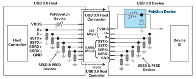
Fig. 1 shows how installing a PolyZen device on the VBUS as well as six low-capacitance Silicon ESD (SESD) or Polymer ESD (PESD) protection devices on a typical host and device circuit, can help provide a coordinated overvoltage solution.

Fig. 1. PolyZen devices and silicon or polymer ESD protection devices provide a coordinated protection solution on host and device side.
Leakage Current During Suspend Mode for USB
All USB-compliant devices support suspend mode, which generally refers to a sleep state where the device may not consume more than 2.5 mA of current. A device transitions into suspend mode after it remains in a constant idle state on its upstream-facing bus line for more than 3 ms. The device draws a suspend current from the bus after no more than 10 ms of bus inactivity on all of its parts.
Some electronic devices have the capability to generate remote wake up signals. This enables the device to transition back to normal mode of operation from the sleep state.
The USB 2.0 specification states that all electronic equipment, either low- or high-power, must default to low power during suspend state. This means that when operating at low power, low-power devices such as flash drives or high-power devices such as external HDDs are limited to just 500 µA of suspend current (that is, 1/1,000th of the rated current during normal operation mode).
USB-enabled devices with the capability of generating remote wake up signals are allowed (as per the spec) to draw up to a maximum of 2.5 mA during suspend mode. This also holds true for configured bus-powered devices. Each available external port (up to 4 ports) is allocated 500 µA, leaving the remainder available for the hub and its internal functions. An un-configured hub is considered a low-power device and suspend current is limited to 500 µA.
The power control during suspend mode slightly differs for USB 3.0, or “SuperSpeed USB,” host controllers and most of the supporting devices. USB 3.0 does not define a low-power or high-power device. All USB 3.0 devices may draw a current of up to 2.5 mA during suspend mode. Bus-powered compound devices may consume up to 12.5-mA suspend current with 2.5-mA suspend current for each port, up to a maximum of four ports, and 2.5-mA suspend current for internal hub and its functions. The suspend current so defined includes the current from VBUS through bus pull-up and pull-down resistors.
It is always advantageous to have as little leakage current as possible in order to improve the battery life of portable devices. Though typical standby modes consume less power than normal operating modes, leakage current from the CMOS-based devices used may still occur. The leakage current, if high enough, can wake up the device from sleep mode.
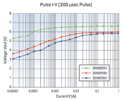
Fig. 2 shows I-V comparison curves of pulse length at 300 µs for three low-power PolyZen devices. As shown on the graph, the leakage current for the PolyZen ZEN056V device varies from 1 mA at 4.75 V to 4 mA at 5 V. For the PolyZen ZEN065V device the leakage current at 5 V is close to 5 µA; however, its typical clamping voltage at 100 mA is 6.5 V. The third device depicted on the chart, the ZEN059Vdevice, has a typical current consumption of 500 µA at 5 V.
The low-power-consumption ZEN059V device bridges the gap between the ZEN056V and ZEN065V devices by providing both low clamping-voltage and low current-consumption (at 5 V). This device helps protect downstream electronics sensitive to voltages above 6 V.

Fig. 2. I-V comparison curves of PolyZen devices at pulse length at 300 µs.
Summary
Polymer-enhanced zener diodes offer designers the simplicity of a traditional clamping diode while obviating the need for significant heat sinking. This integrated device helps provide protection against the use of improper power supplies, as well as protection from damage caused by overcurrent events. Low-power-consumption PolyZen devices also provide low leakage current during suspend mode, making them a suitable overvoltage protection solution for USB controllers and compliant devices.
■
Advertisement
Learn more about TE Connectivity


