Power converter brings high efficiency to HVAC
Sophisticated electronic controls yield significantly better energy efficiency
BY SILVESTRO FIMIANI
Power Integrations
San Jose, CA
http://www.powerint.com
In the design of heating and air-conditioning systems, the combination of high-efficiency heat exchange techniques and sophisticated electronic controls yields better energy-efficiency ratings. A highly efficient and rugged power supply provides the basis for efficient motor drives and reliable system performance.
With the cost of crude oil nearing $100 a barrel, the gains to be made from energy efficiency are greater than ever. In the industrial/domestic sector, this is particularly true for area heating or in heating appliances.
An example application
The condensing boiler is one example of heating technology that offers higher efficiency by making use of the basic principles of thermodynamics. Modern electronics enables performance gains close to the theoretical maximum to be obtained.
A high-efficiency condensing boiler incorporates a large heat exchanger to extract the maximum energy from the flue gases. It produces lower flue gas temperatures, lower emissions, and reduced fuel consumption. It typically converts more than 88% of the fuel used into useful heat, compared to, typically, 78% for a conventional boiler.
Recovering the heat from the flue reduces the temperature of the flue gases to where water vapor produced during combustion is condensed out, thus the name “condensing boiler.” The process of condensation is key because, as water changes from the vapor to liquid state, it releases the latent heat of vaporization, a more significant source of energy than the transfer of heat by cooling the vapor alone.
The natural buoyancy of the flue products is lost when the temperature is brought down, so it is necessary to have a fan in the flue to maintain the flow of exhaust gases. The fan’s speed is controlled to maximize efficiency. A high-efficiency power supply capable of operating reliably in a high-temperature environment is required to power the fan, the system timer, and control electronics,
A design that perfectly fits the bill
A similar power conversion requirement occurs in air-conditioning equipment and white goods such as dishwashers and washing machines, particularly those with integrated condensing dryers.
Take, for example, a switch-mode power supply (SMPS) capable of delivering a constant 50 W at 24 V and a peak loading of 70 W at an ambient temperature of 65°C without an external heat sink. Its peak loading capability enables the high currents required for motor startup to be delivered from components sized to support the continuous load, for significant size, cost, and weight reduction.
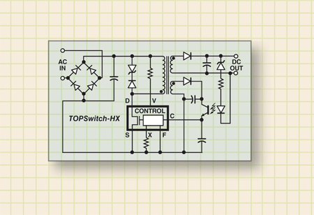
Many integrated switch/controller devices are available. One design example described here is built around a TOPSwitch-HX controller IC from Power Integrations. The controller incorporates a 700-V power MOSFET, a high-voltage switched current source, a multimode PWM controller, an oscillator, a thermal shutdown circuit, fault protection and, other control circuitry onto a single monolithic device (see Fig. 1 ).

Fig. 1, A typical TOPSwitch-HX flyback application has the most of it’s required components in the integrated switch/controller device.
The device switches seamlessly between four different modes of operation depending on the load conditions. This enables the SMPS to operate at constant high efficiency over an exceptionally wide power band and still be able to provide more than 600 mW of output power for only 1-W input in standby mode. These features allow the supply to meet existing and proposed energy conservation standards worldwide.
Other design features
The switch/controller also features enhanced user-defined protection features in line undervoltage and overvoltage and output overload conditions. It provides output overvoltage protection configurable for latching or self-recovering modes, thermal shutdown, and auto-restart. Careful control of key parameters significantly reduces maximum overload power, which in turn allows the use of lower-cost power train components (MOSFET, transformer, and output rectifiers). Improvements in silicon technology have provided a plastic DIP with a 1.8-Ω on-resistance MOSFET (TOP258P), versus 3 Ω minimum in the previous generation. Coupled with a low 66-kHz switching frequency, this enables the elimination of the external heat sink in many applications.
The switches features also offer benefits to white goods. The dual in-line P package incorporates >3.2 mm creepage/clearance between high-voltage pins to prevent surface leakage currents occurring in high-humidity and polluted environments. The thermal shutdown is auto-recovering and incorporates a wide hysteresis to maintain safe PCB temperatures under any fault condition. The auto-restart function protects against output short circuits and open feedback loops. These improved safety features fully protect the power supply and load under fault conditions and can prevent overheating or even a fire, a significant factor with appliances commonly being run unattended at night.

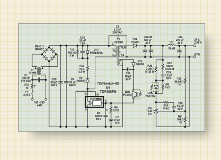
Fig. 2. A 50-W continuous, 70-W peak, SMPS designed around the switch/controller IC provides an efficient, reliable circuit.
Design details
Figure 2 shows the complete SMPS circuit. The design meets EN55022 and CISPR-22 Class B conducted EMI limits with significant margins. Differential EMI filtering is implemented with X-capacitor C1 , while common mode EMI filtering is accomplished by common-mode choke L1 and safety rated Y-capacitor C8 . A metal film type capacitor, C4 , located physically close to the switching circuitry, helps to decouple high-frequency noise from the DC bus and improve differential EMI.
An RCD clamp is formed by D2 , R17 , and C34 to prevent drain voltage spikes from damaging the integrated MOSFET in U4 . Zener diode VR1 is in place to assure the maximum clamp voltage and does not conduct under normal operating conditions. A bias winding on transformer T1, which is rectified by D13 and filtered by C13 , powers the Switch and provides the control current for optocoupler U2 .
Output feedback is provided via U2 , whose bias point is set through the TL431 shunt regulator U3 and R10 and C36 provide compensation for the feedback network. R27 and C35 form a network that helps improve phase margin, while R9 provides a bias current to the shunt regulator, U3 , when the optocoupler, U2A, is not conducting. R26 sets the overall loop gain as well as limiting the current through U2A during transients.
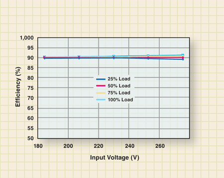
Key conversion features enable high-efficiency application. The SMPS operates over a wide supply input range of 185 to 265 Vac. The designs key specification is it’s exceptionally high efficiency maintained over the complete input voltage range (see Fig. 3 ).

Fig. 3. Efficiency versus load, across all line voltages.
And, as mentioned previously, the supply operates at a high efficiency over an exceptionally wide power band, including more than 600 mW of output power for only 1 W input in standby-mode. A complete description of the design may be found in “Design Idea/DI-144,” available at www.powerint.com. ■
Advertisement
Learn more about Power Integrations


