By BOB CANTRELL
Senior Application Engineer
Ericsson Power Modules
www.ericsson.com
Prolonged exposure to high operating temperatures is known to be one of the greatest enemies of electronic components, accelerating failure of semiconductors and promoting other wear-out mechanisms such as drying of wet electrolytic capacitors. For every 10°C rise in operating temperature, life expectancy decreases by about 50%, according to the rule of thumb. Conversely, reducing the temperature by 10°C can double the expected reliability.
Internal heat dissipation caused by inefficiency in the conversion process is a major contributor to excessive operating temperature. In effect the equipment operator pays twice for inefficient power conversion: Every watt dissipated is another watt that must be cooled, hence demanding extra air-conditioning or cooling capacity to keep the ambient temperature within specified limits as total system power dissipation increases. Clearly, improving energy efficiency can improve reliability and reduce operating costs by reducing the demand for system cooling.
However, another figure of merit for power converters is current density. Higher current density means smaller devices for a given power rating, which ultimately allows system designers to use more of the expensive board real estate for revenue-generating devices, such as processors, ASICs, or FPGAs, that add functionality. Moreover, small PoL converters, in particular, can be placed closer to the power pins of the main ICs on the board for the best possible transient performance.
Desirable characteristics are for a converter to be simultaneously smaller, more energy-efficient, and with excellent heat-dissipating properties. Dealing effectively with heat is critical to maximizing current density or to power-handling capability. A good analogy is to consider two runners of equal height, weight, and fitness running in hot conditions, such as at midday in the Arizona desert. The only difference is that one is wearing suitable lightweight running gear, while the other is wearing a thermal outfit that prevents heat from leaving the body. On paper, both can achieve the same performance. But the second runner will not be able to shed the heat his body is creating as efficiently as the first and soon will be unable to continue running.
Solving the dilemma, digitally
Digital technology can help to overcome the challenges facing power conversion. For example, digital converters can be smaller because they require fewer components than a conventional analog converter topology. The reduction in component count also helps to boost reliability. In a digital converter, the output voltage is sensed in the same way as in an analog design, but there is no error amplifier. Instead the sensed voltage is digitized by an A/D converter, and the digitized values are input to a control algorithm hosted on a microcontroller. Various algorithms can be used to optimize performance as the operating conditions change. Fig. 1 illustrates the main functional blocks of a digital converter.
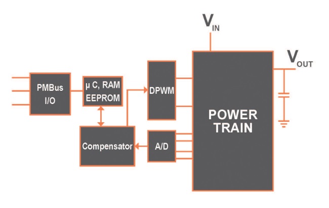
Fig. 1: Digital power conversion simplifies circuit design and reduces component count.
Converters such as Ericsson’s 3E single-phase PoLs feature advanced energy-optimization algorithms to enhance efficiency across the load range. Also, with a specific input voltage, output voltage, and capacitive load, these converters permit the control loop to be optimized for a robust and stable operation and with an improved load-transient response. This optimization minimizes the amount of output decoupling capacitors needed to achieve a given load-transient response, optimizing cost and minimizing board space. This effectively simplifies hardware design, reduces overall module size, and helps to boost reliability. Fig. 2 shows how digital converter technology enables designers to boost efficiency at light loads, for which traditional analog converters are often less efficient.
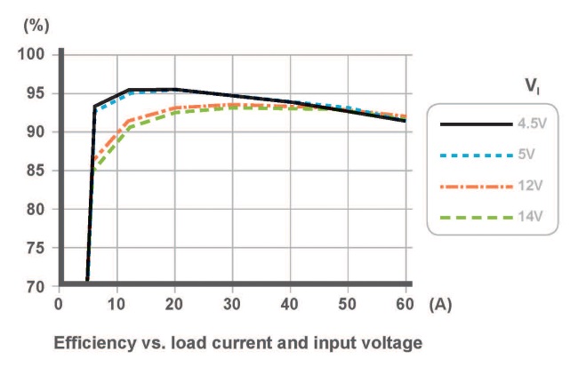
Fig. 2: Digital power converters can deliver significantly higher efficiency at light loads.
Other aspects of the 3E PoLs that help enhance efficiency include the latest-generation power MOSFETs, which have low internal capacitances and optimal on-resistance x gate-charge figure of merit (RDS(ON) x Qg ) to minimize conduction and switching losses at all times.
The latest converter in the family, the BMR466, can deliver up to 60 A and has been shown to achieve efficiency of 94.4% with a 5-V input and a 1.8-V output, at half load. The MTBF of the BMR466 is calculated at 50 million hours based on the industry-standard Telcordia method.
As many as eight BMR466s can be connected, allowing designers to rely on a single part number when powering applications between 60 A and 480 A. It is also possible to synchronize two or more BMR466s with an external clock to enable phase spreading, which helps lower input ripple current and, therefore, effectively reduces capacitance requirements and efficiency losses.
Advanced thermal performance
The internal design of the BMR466 is optimized to achieve a low package profile. Its height of 0.276 in. (7 mm) minimizes interference with cooling airflow across the board. Moreover, the solder pad distribution of the LGA package gives excellent thermal performance and enables the module to dissipate heat very efficiently while benefiting from an extremely compact footprint of 0.98 x 0.55 in. (14 x 25 mm). The LGA contacts are positioned symmetrically to ensure superior mechanical contact and high reliability after soldering. Internally, the package technology eliminates connecting leads and their associated inductance, and a high number of the LGA contacts are ground pins. Together, these features ensure excellent noise and EMI characteristics.
Improving thermal performance is the key to minimizing thermal derating, allowing higher output current without sacrificing reliability. Fig. 3 shows thermal derating curves for the BMR466 with an output of 1.0 V, which can deliver the maximum 60 A at an ambient temperature of 70°C with natural convection cooling alone. For an ambient air temperature of 85°C, the converter can deliver 48 A cooled with natural convection, or 55 A with airflow of 1.0 m/s.
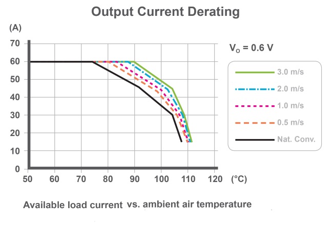
Fig. 3: Thermal derating for BMR466 PoL converter with 1.0-V output.
The derated current capability of the BMR466 is comparable to that of competing PoLs that have more than twice the surface area and occupy nearly four times the volume, even though these have higher maximum current ratings. Consider the derating curves for a competing 80-A PoL, seen in Fig. 4, which show that the higher-rated converter has a real-life limit of 62 A for an ambient air temperature of 70°C with natural convection with a 1.0-V output. While this competing converter can deliver up to 60 A at 85°C ambient temperature, with 1.0-m/s airflow, this is only marginally higher than the 55 A available from the BMR466 operating under the same conditions even though the BMR466 is significantly smaller.

Fig. 4: Thermal derating curves for alternative 80-A PoL with 1.0-V output.
The larger 80-A PoL has little more than one-third the current density of the BMR466. Considering that a single computing board for an application such as a data center server may need several — sometimes 10 or more — high-current PoLs, the cumulative space savings that can be achieved, without derating the maximum current or degrading reliability, are significant and valuable.
In addition, the digital converter can be configured via a GUI such as Ericsson’s Power Designer software to ensure optimal efficiency and performance, the lowest BOM cost, and optimized transient response. This tool gives system architects control over parameters such as switching frequency and threshold settings for input and output under-/over-voltages, output over-/under-current limits, and over-/under-temperature to ensure optimum efficiency under a range of operating conditions. In addition, using phase spreading, the input ripple current can be dramatically reduced, thereby reducing input capacitance requirements and efficiency losses.
Advertisement
Learn more about Ericsson Power Modules


