Power dissipation of bulkwave quartz xtal units
The designer should understand the methods used to maintain the power of a quartz crystal unit in an oscillator configuration
BY SHAWN LOGAN
LSI, Milpitas, CA
http://www.lsi.com
Bulkwave quartz crystal units form the resonant elements of oscillators as well as voltage-controllåed oscillators designed to exhibit excellent long- and short-term frequency stability. The roots for the use of bulkwave quartz to control an oscillator’s frequency dates to 1919 when Prof. W. G. Cady at Wesleyan University described the use of a piece of quartz to control an oscillator’s output frequency. Despite its deceptively simple schematic, the nonlinear behavior of the oscillating amplifier and its nonlinear quartz crystal unit continues to be the subject of active research and development.
One aspect of the oscillator design process is the power dissipation of the bulkwave quartz crystal unit in an oscillator configuration. Its power dissipation can vary tremendously as a function of its operating point in the oscillator. Bulkwave quartz crystal units whose power dissipation is low can exhibit anomalously nonlinear behavior that results in intermittent oscillator startup issues or a different frequency-temperature behavior than when dissipating larger amounts of power.
In contrast, excessive power dissipation of a bulkwave quartz crystal unit can result in unnecessary circuit power, premature aging, and even breakage for some specific types of quartz crystal units. The focus of this article is to provide enough background information on quartz crystal units and oscillators to allow a designer to specify the power dissipation of a bulkwave quartz crystal unit and to understand methods that may be used to maintain the power of a quartz crystal unit in an oscillator configuration within a range compatible with a specified quartz crystal unit.
Butterworth Van-Dyke model
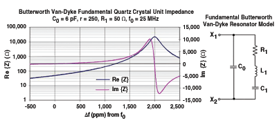
The fundamental resonance of a bulkwave quartz crystal unit can be modeled using the Butterworth Van-Dyke model shown in Fig. 1 . The motional arm, consisting of elements R1 , L1 , and C1 , models the piezoelectric behavior of the quartz blank. C0 models the capacitance between the two electrodes of the quartz resonator and includes the package capacitance between the two terminals X1 and X2 . The value of C0 may be increased by the presence of additional board-level capacitance between the two crystal unit terminals.

Fig. 1. A Butterworth Van-Dyke mode quartz crystal unit model.
The real and imaginary parts of the driving point impedance between X1 and X2 of a 25-MHz AT-cut quartz crystal about the resonant frequency of its motional arm (ω0 = 2πf0 = 1/√L1 C1) are overlaid in Fig. 1. Intuitively, for frequencies far below and far above the series resonant frequency of the motional arm, the impedance is dominated by the impedance of the electrode capacitance C0 .
Near the series-resonant frequency of the motional arm, the impedance is governed by the resonant behavior of the motional arm. Very near the motional arm series resonant frequency, the real part of the impedance is approximately equal to the resistance R1, and the imaginary part of the impedance is approximately zero.
Quartz crystal in an oscillator configuration
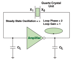
A common Pierce quartz crystal unit oscillator topology whose frequency is primarily determined by a quartz crystal unit is illustrated in Fig. 2 . In steady-state operation with the frequency of operation approximately equal to the series resonant frequency of the quartz crystal unit, the open-loop gain and open-loop phase are unity and a multiple of 2π, respectively.

Fig. 2. A common Pierce quartz crystal unit oscillator topology has a frequency that is primarily determined by a quartz crystal.
The Pierce topology may promote the buildup of steady-state oscillation near the series resonant frequency of the quartz crystal if its nonlinear gain is greater than some minimum value and its nonlinear delay provides sufficient phase shift to satisfy the phase shift requirement near the series resonant frequency of the quartz crystal unit. If oscillation ensues, the amplitude envelopes of the input and output amplifier waveforms will increase with time as the amplifier delay changes until the steady-state oscillation conditions are satisfied. In many cases, the amplifier gain reaches a steady-state value of unity when the peak-to-peak output waveform amplitude reaches the difference in its supply voltage and ground.
In steady-state oscillation, the power dissipation of the resonator may be established by considering the rms value of the waveform across the quartz crystal unit and the impedance of the crystal unit at the oscillation frequency. In essence, if the oscillation frequency of the resonator is known relative to its series resonant frequency and the rms amplitude of the resonator waveform at the frequency of oscillation are known, the power dissipated in the resonator may be determined.
Power dissipation in a resonator model
Physically, the fundamental mode Butterworth Van-Dyke resonator model contains a resistive term R1 to model the losses of the piezoelectric material operating near the fundamental frequency. If a sinusoidal voltage source with an rms voltage Vrms is applied across the resonator model and its frequency is swept from a frequency below the series resonant frequency of the resonator (ω0 = 1/√L1 C1 ) to a frequency above the series resonant frequency, the power dissipated in the resonator may be determined as a function of the frequency of the driving source, ω0 ) relative to the series resonant frequency as detailed in Eq. (1)

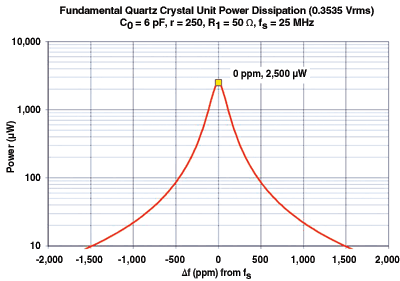
As the driving source frequency approaches the series resonant frequency of ω0 , the power dissipation of the resonator reaches a maximum of Vrms2 /R1 . As the difference between the driving source frequency and ω0 , increases, the power dissipation of the resonator decreases.

Fig. 3. A plot of crystal unit power dissipation as a function of frequency for a specific 25-MHz bulkwave crystal unit.
A plot of crystal unit power dissipation as a function of frequency for a specific 25 MHz bulkwave crystal unit is shown in Fig. 3 . The maximum power dissipation is observed to be 2,500 µW at the series resonant frequency.
Implications
To establish the power dissipation of a crystal unit in an oscillating amplifier, the amplifier’s steady-state, large signal, input capacitance must be determined in order to locate the corresponding operating point on the quartz crystal unit impedance characteristic. It is evident that to reduce the power dissipation of the quartz crystal unit, the operating frequency of the oscillator must not be at the series resonant frequency of the quartz crystal unit. This suggests the input capacitance of the amplifier must be low to present a high input reactance to the quartz crystal unit.

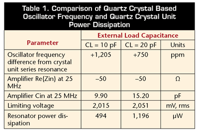
By changing the value of load capacitances CL in the oscillator shown in Fig. 2 from, for example, 10 to 20 pF, the operating point of the steady-state frequency and crystal unit power dissipation changes. Table 1 illustrates the oscillator steady-state frequency and crystal unit power dissipation for a 25-MHz AT-cut bulkwave quartz crystal unit with a C0 of 6 pF and a resistance of 50 Ω. The steady-state oscillator frequency increases by 455 ppm from series resonance in response to a decrease in CL from 20 to 10 pF. However, the power dissipation of the quartz crystal unit is decreased from 1,196 to 494 µW when CL is decreased from 20 to 10 pF.
In applications where the power dissipation of the crystal unit is an important parameter, the input reactance of the oscillating amplifier and the limiting voltage across the crystal unit must be chosen to be in a range that meets the resonator power dissipation limits. ■
Advertisement
Learn more about LSI


