Global demand for electricity has increased significantly over the last decade and is expected to double by 2030. In parallel, there are concerns of energy supply and distribution. Coal and natural gas are being strongly challenged due to carbon emissions, and nuclear power due to safety issues. Renewable energy, primarily solar and wind, has gained a lot of attention and has proliferated across several countries. Increased efficiency, reduced cost, and reliability are three areas where renewable-energy systems can achieve grid parity. These systems are rapidly advancing on these fronts as they become more intelligent, more loss-less, and smaller in size through increased content in digital and analog power electronics — semiconductor switches, drivers, controllers, and sense elements.
This article discusses advances in power components, particularly ICs in solar (also called photovoltaic or PV) inverter systems. The goal is to maximize system efficiency through power management control and maximum power point tracking (MPPT). Therefore, particular focus is made on digital controllers that have gained a lot of traction in recent years.
Power conversion in photovoltaic systems
The front end of the PV ecosystem are the PV panels that are made up of cells connected to each other in series or parallel. These cells convert sun light to electrical energy at efficiencies that typically range from 10% to 30%. The power extracted from the panels is dc and needs to be converted to ac, regardless of whether the PV system is grid tied or off-grid. Conversion from dc to ac power happens in the back end of the PV chain in the inverter. In the case of an off-grid PV system, within the PV inverter an additional dc/dc converter is needed to charge the batteries.
The inverter function
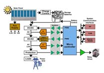
PV inverters (see Fig. 1 ) generate a sinusoidal ac waveform at a fixed level from a dc source — PV panels with varying voltages. The output voltage and frequency need to be at a certain level and, if the inverter is connected to the power grid, need to be synchronized with the power-line. Single-, two-, and three-phase types are available for different applications. In addition to power management controls, the inverter performs other tasks, such as maximum power point tracking, monitoring, protection, and communication.

Fig. 1: Block diagram of a photovoltaic inverter.
Inverter configuration
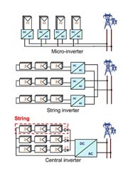
In general, there are three inverter configurations as shown in Fig. 2 . Each depends on the power levels. A micro-inverter is a low-power configuration. A medium power configuration between 1 kW to 20 kW is called a string inverter, and a high-power configuration greater than 20 kW is called a central inverter.
All inverter configurations follow the same methodology for power conversion, however, there are variations in the power conversion topology for inverter efficiency maximization. The choice of power switches (MOSFETs or IGBTs) and the number of switches and drivers employed varies by topology, which is critical for cost optimization and reliability.

Fig. 2: Inverter configurations.
Key inverter components and their role in increasing efficiency
PV inverters are built much like switch-mode power supplies. Here are the key components of an inverter:
- Controller that performs the power management, MPPT and off-line storage (batteries)
- Power semiconductor switches — IGBTs, MOSFETs
- Gate drivers to switch the power devices
- Feedback sensing elements — voltage and current sensing
- Auxiliary bias supplies
- Communication devices
- Passive elements
- Transformers for galvanic isolation and to adjust the voltage levels in some topologies
Power losses in semiconductor switches and gate drivers are key concerns for efficiency. Keeping the loss in capacitors and magnetic elements, such as inductors and transformers, close to zero is also critical.
Inverter topology
In the inverter system, to operate a dc-to-ac converter, the input voltage usually needs to be above the output voltage. To generate a sinusoidal waveform of 230 Vac, an input voltage higher than 400 Vdc is necessary. The problem is that PV modules often deliver lower voltages than required for the dc/ac converter. There are two ways to resolve this issue. One is to use a boost dc/dc converter between PV panels and the dc/ac converter. The other is to use a transformer after an H-bridge in dc/ac conversion. For the latter design, there are three fundamental topologies for inverters:
- Low-frequency transformers (50-60 Hz) (LF)
- High-frequency transformer (HF) and
- Transformer-less inverters (TL)
The majority of U.S. market uses LF and HF (transformer-based) inverters, as mandated by standards, whereas the majority of the European market uses TL inverters. In the Japan market, there is an fairly equal split.
In LF inverters, the transformers are bulky and large, and lower efficiency by 2% to 3%. HF inverters operate greater than 60 Hz, and weigh and cost less. TL inverters weigh less as they have no transformers. They also have increased efficiency due to the absence of the transformer in the system.
The LF inverter is a single-stage system where power is directly converted from dc to ac, whereas HF and TL inverters are two-stage systems. Stage one is for dc/dc conversion — the primary-side. The second stage is for dc/ac conversion — the secondary side. Typical primary-side circuits employed are boost, buck-boost and interleaved flyback (for HF). Figure 3 shows a TL inverter design.

.
Fig. 3: TL inverter design
Dc/dc stage
The primary side of the inverter performs a key function of MPPT. The MPPT algorithm ensures that maximum power is drawn accurately and quickly while there is varying irradiance and ensures that the inverter always delivers the appropriate voltage that is grid-compliant. Finer control of MPPT is dictated by the inverter configuration. Finest control is achieved in micro-inverters, which are connected at the back of each solar panel. This enables MPPT at a module level, followed by a string inverter connected to a series of modules with lesser control. Both configurations are usually employed in residential and commercial installations. The central inverter connected to a large set of modules at a utility scale gives the lowest control.
The same digital controller is responsible for gate driver control in the primary side. PWM takes place using gate drivers. These drivers do not require isolation. Given that the bus voltage is less than 600 V and high switching frequencies are used in the primary side, power MOSFETs are ideal for dc/dc conversion. Depending on the topology, single, dual, or half-bridge MOSFET drivers are used with fast propagation delays and high drive currents. Today's commercial inverters use silicon MOSFETs. Next-generation inverters are evaluating GaN (gallium-nitride) and SiC (silicon-carbide) FET solutions that offer lower conducting and switching loss solutions.
Dc/ac stage
The dc/ac stage, or the secondary side, uses the H-bridge circuit. This involves four power switches for a single-phase solution, and 12 for a three-phase system. Here, the switching frequency is usually a few kilohertz. However, the rail voltages are in the order of 600 to 1,200 V, particularly in string and central inverters, making IGBTs the right choice for switching.
With the goal of reducing the conducting loss in the secondary side for efficiency improvement and the high blocking voltage requirement, SiC MOSFETs have gained attention in the development of next-generation inverters. Gate drivers needed to switch IGBTs used today require advanced features such as desaturation, short-circuit current protection, Miller clamping, and negative voltage handling.
Furthermore, several isolation technologies, currently being developed and commercialized, are getting integrated into these gate drivers. These requirements are driven by safety standards for signal isolation. Moreover, several ICs have been developed for output-stage drive solutions that provide extra drive capability that discrete solutions used to provide, as well as level-shifting and protection features.
Components
Gate drivers such as Texas Instruments’ UCC27531 and UCC27210 are key elements to efficient and reliable solar power conversion. Digital and analog controllers such as TI’s UCD3138 and C2000 real-time control Piccolo microcontrollers are available for efficient PWM and MPPT control.
Advertisement
Learn more about Texas Instruments


