Ac to dc conversion is a fundamental step in many electronic products
BY PAUL YEAMAN
Vicor
Andover, MA
http://www.vicorpower.com
Ac-to-12-Vdc conversion is a fundamental step in many electronic products today. However, the real challenge is to achieve a small, efficient package with high reliability and easy scalability. Let’s consider the various stages in that process, taking a typical lower-power server system as an example.

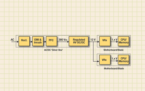
The basic flow is a full-bridge ac rectifier followed by EMI/inrush protection, then a power factor correction (PFC) stage creating a 380-Vdc rail. This is down-converted to a 12-V line, distributed through the system to each motherboard/blade and then down-converted again to the load voltage.
Power factor correction
Let’s begin with the PFC stage. “Power factor” is the relationship between voltage and current waveforms and is a measure of “power quality” that affects transmission network efficiency.
PFCor rather the associated total harmonic distortion (THD) performanceis a requirement for more than one-third of the world’s population as defined by specifications in Europe (EN61000-3-2), Japan (JIC C 61000-3-2) and China (China Compulsory Certificate). Whereas lower-power applications (up to ~200 W) may use simple discontinuous conduction mode (DCM) boost PFC, continuous conduction mode (CCM) is required for a server’s power levels.
The classic CCM PFC controller has been the UC3854 “multiplier” IC in SO16, but new, simpler designs may now be completed with the ‘one-cycle control’ technique as used in the SO8-packaged IR1150.
EMI/inrush protection
The PFC and EMI/inrush protection stages can be completed using discrete designs but can be complex and require a high degree of “skill plus art” to perfect. An alternative is to use a ready-made front end solution such as the FE375 which accepts universal (worldwide) ac voltage, contains an EMI filter plus inrush protection (EN61000-4-4 and EN61000-4-5) and creates up to 2.2 kW at a regulated 375 V with auxiliary 14-V outputs and achieves a 28-W/in.3 power density.
Once we pass the 380-V point, we now need to consider how many regulation stages are required. At first glance, this may seem like an odd question but if our server’s downstream system goes from 12 V to 1.x V (for the processor or memory) via a voltage regulator stage (VRM or VRD), then having a regulation function in the high-voltage dc/dc converter could be redundant. This redundancy increases size, losses and cost.
Most server ac/dc SMPSs tend to be above 800 W and so use regulated two-transistor forward converters or full-bridge converters to reach 12 V (potentially also via an output ORing stage for n + 1 redundant systems). These topologies are tried and trusted but are now running out of steam in terms of efficiency and power density.
By utilizing the downstream VRx regulation, we can replace the high-voltage regulated dc/dc stage by a high-voltage unregulated bus converter system. As bus converters are “simple” isolated dc-transformers, relying on a 50% duty cycle and their internal transformer turns ratio for conversion, they are most effectively designed using resonant techniques.
For telecom converters running from narrow-range 48 V down to 12 V, an unregulated bus converter has 3% higher efficiency than a regulated converterand is half the size. We can apply the same analysis to high-voltage (380 to 12-V) dc/dc conversion inside ac/dc power supplies.
High-voltage bus converters
As with the PFC/EMI front-end, high-voltage bus converter designs can be completed using discrete components or completed power components. The L6599 is an LLC resonant half-bridge controller IC that has become a common part in LCD and PDP TV power supplies.
However, this device runs out of steam when addressing our server system’s power needs so an alternative such as the full-bridge IR2086 is requiredthough this uses a low-voltage technology so it must be secondary referenced with pulse transformers for the primary-side MOSFETs.

A low-power server is a good ac-to-12-V application to examine.
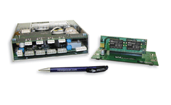
These ICs use resonant techniques but are limited to switching frequencies in the 100s of kilohertz and so still have large magnetics and are unable to achieve high power densities. For a ready-made solution, the B384F120T30 is a complete 300-W LC-resonant high-voltage bus converter running at more than 1 MHz with a power density of over 1,000 W/in.3 The B384 can drop into the ac/dc “silver box,” replacing the traditional regulated high-voltage stage and converts from the post-PFC 380 V directly to the 12 V for distribution though the server system.
The “building-block” flexibility of the HV B384 means that we can address the high-current/low-efficiency (I2 R losses) distribution issue. By moving the HV bus converter onto each motherboard/blade, we bus 380 V, rather than 12 V, through the system. At the same time, the 12 V is generated immediately next to the VRx, making distribution loss through bus bars and connectors negligible.
Incidentally, capacitance multiplicationa capability that can bear on the need for small sizeis an integral characteristic of the bus converter module. The bulk capacitors, normally on the input of the nonisolated VRx, can be moved to the input of the bus converter module. As the energy stored in a capacitor is proportional to V2, this reduces the capacitance by 1,000X and eliminates the bulky caps at the point of load. ■
Get more information on dc/dc converters at http://electronicproducts-com-develop.go-vip.net/power.asp.
Advertisement
Learn more about Vicor


