Power modules for variable-speed motor control
Energy savings of 30%, improved reliability and quiet operation can be achieved at low overall cost
BY JONAH CHEN and VIJAY BOLLOJU
International Rectifier
El Segundo, CA
http://www.irf.com
Demand is growing for appliances such as washing machines, refrigerators, and air conditioners to help improve domestic energy efficiency. Moving from conventional fixed-speed motors to variable-speed operation could save as much as 30% of energy consumed, but appliance vendors must deliver this increased efficiency at little or no extra cost to end users. Several solutions have emerged to ease the digital design of such a project, but designers also need integrated modules and associated design tools to facilitate design of the power stage.
To enable low-cost variable-speed motor controllers, component vendors have sought to reduce the cost of the variable-speed controller, which is the most expensive part of the system, by making the design easier and reducing build complexity. For example, several digital signal controller platforms have emerged, combining DSP and RISC processors with integrated PWM and motor-control peripherals. These provide a programmable platform capable of hosting a third-party or in-house motor control algorithm.
Alternative solutions are available that implement the motor control algorithm directly in hardware, which eliminates software development and integration challenges and also speeds up algorithm execution to enhance torque and speed control.
Whichever solution is preferred, the digital control challenges can now be solved quite quickly. However, the other major hurdle is to design and integrate the power stage. Configuring a suitable inverter, gate driver, and associated protection circuitry requires considerable power electronics design skills.
Integrated power modules
An integrated power module (IPM) combines all of the aforementioned elements into a single unit, reduces design time and delivers additional benefits including reduced component count and increased reliability.
The IPM absorbs much of the engineering effort associated with complex power system design for motion control applications. For example, gate impedances are preoptimized for lower EMI noise and power loss, and bootstrap diodes and resistors are also integrated to drive high-side IGBTs.
Driver layout challenges are addressed to minimize losses due to parasitic effect and to maximize thermal performance, and protection against over-current and over-temperature is also built-in. The engineer simply has to choose the right IPM for the intended application.
However, even this can be a daunting task. The performance of the IPM in a system depends on many application-related parameters, such as the switching frequency, modulation index, and module case temperature. Datasheets provide some guidance, but usually relate to standard operating conditions. Designers need extra help to predict performance in a specific application.
In order to choose the right IPM, the engineer starts with information about the application. For example, consider a washing machine controller intended for operation at up to 3-A rms phase current and 16-kHz switching frequency, with dc bus voltage 320 V. If enhanced reliability is an intended selling point for the end-product, the specified maximum junction temperature may be set well within the module vendor’s recommended limit; say 125°C.
Current ratings, heat sinks
The IPMs are available in a number of current ratings and more than one choice may be is suitable for this application. However, because the power losses will be different for each module under the given operating conditions, the heat sink necessary to maintain junction temperature under 125°C will also be different. Calculating the required heat sink thermal resistance (RTH ) requires complex knowledge of IPM thermal and electrical behavior to identify conduction and switching losses and predict the junction temperature based on these data.
Although modeling steady-state conditions is relatively straightforward, the power losses in practice are not constant. In operation, the junction temperature will fluctuate beyond the steady-state average because power losses vary at a fundamental frequency equivalent to the modulation frequency of the inverter.
Another important aspect is mutual heating, since the multiple heat sources within the IPM share the same paths from case to ambient. This effect must be taken into account if the model of the IPM is to be accurate.

Fig. 1. A modeling tool user interface with menu-style parameter entry.
Modeling tools
Detailed models of IPMs power modules can be a great benefit when identifying and selecting appropriate modules. The module suppliers often have custom tools to with electrical and thermal models for currently available modules.
The tools can be used to generate a series of performance curves describing IPM behavior under the application conditions entered by the user. Often the tools allow the users to change parameters such as switching frequency, power factor and modulation index to obtain performance curves customized for the application.
The tools usually allow the user to generate useful information to enable easy selection of IPMs:
Power loss analysis. To produce power loss versus switching frequency curves.Component comparison . To produce power loss and case temperature curves for heat sink selection.

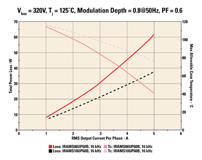
Fig. 2. The design tool graphs of power loss vs. phase current and case temperature.
Considering the earlier design example, The modeling tools can be used to calculate the required heat sink Rth. Figure 1 shows the component comparison analysis result from a typical tool, showing both the power loss of the inverter and the maximum heat sink temperature for this application.
At 3 A rms, the power losses are 31 W for the 6-A module and 21 W for the 10-A module. The maximum allowable case temperature is 84ºC and 99ºC for 6- and 10-A module, respectively. The required heat sink Rth can be calculated as follows:
Rth(S-A) = (TC – TA) / P – Rth(C-S)
The table below shows calculated heat sink Rth values assuming ambient temperature of 50ºC and Rth(C-S) of 0.1ºC/W.
Calculated heat sink Rth values
The calculations indicate that the smaller IPM will require a larger heat sink. The final choice would be made based on total system cost and size, including both the IPM and heat sink.
The same method can be used to select an IPM for an air conditioner application. These typically combine a 400-Vdc bus and PFC front-end. The switching frequency will be lower than a washer application to limit EMI noise. If the application requires 10 ARMS current at 6-kHz switching frequency, the tool can show the tradeoffs between 16- and 20-A IPMs.

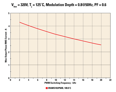
Fig. 3. GThe tool graphs shows the maximumof output current at various switching frequencies.

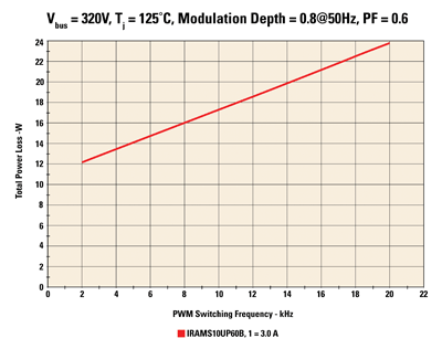
Fig. 4. The tool graphs power loss compared toand switching frequency as shown by the design tool.
This tool can also be used to analyze the effect of modulation index, switching frequency, heat sink temperature, and power factor on the current rating of the module. For example, one design parameter is the switching frequency. The tool can be used to investigate the maximum motor current and power losses of the IPM at different switching frequencies, as shown in Figs. 2 and 3. Selecting up to three parts in each type of analysis shows the power losses increasing and maximum current decreasing with higher switching frequency. ■
For more on motor control modules, visit http://www2.electronicproducts.com/BoardLevel.aspxhttp://electronicproducts-com-develop.go-vip.net/power.aspx.
Advertisement
Learn more about International Rectifier


