It’s through careful refinements in the design that real reliability and efficiency improvements appear
BY GARY BOCOCK
XP Power
Sunnyvale, CA
http://www.xppower.com
Most electronics engineers can design an ac/dc power supply based on first principles but it’s through careful refinements in the design that real reliability and efficiency improvements appear. Here, the technical director of a leading power supply manufacturer shares some of the tips and tricks he used in recent small form factor power supply designs.
Basic mechanical considerations
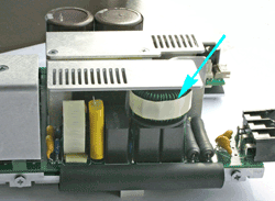
Targeting an industry standard enclosure makes your power supply applicable across a wider range of applications. Making terminals and fuses easily accessible will also increase its appeal, while physically stacking inductors and capacitors in filter networks is a good way of maximizing available space, as well as optimising for EMC performance. Also, the same approach taken to low-voltage circuit layout should be extended to power supplies; try to ensure component placement follows a “left in right out” flow, making them easier to produce and test.

Fig. 1. Inductor stacked on top of capacitor to maximise available space.
Passive components at the input
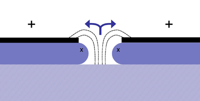
Filters and capacitors at the input stage are essential, they also play a crucial role in overall reliability. But don’t be tempted to go for the smallest, as ceramic capacitors have been known to fail magnificently from input spikes. Metallized polypropylene capacitors, on the other hand, are not only capable of surviving spikes, but also demonstrate a ‘self healing’ property, meaning the power supply keeps working, which makes up for any size penalty over ceramic types.

Fig. 2. The electrical breakdown results in the dielectric being pushed apart demonstrating the self-healing property. ‘X’ indicates the area from which the metal foil has been removed as the arc explodes outwards.
Sufficiently large aluminium electrolytics will ensure that a brief power disruption at the input doesn’t result in lost voltage at the output. By selecting devices rated at around 120% of the maximum rated voltage, capacitors experience a longer working life. Also, use a device specified with a higher than necessary temperature rating, too, which will also extend the operating lifetime. Electrolytics providing a hold-up time in the order of 20 ms can be large, with a correspondingly large equivalent series resistance. At higher frequencies this can result in lost performance, so use smaller capacitors in parallel to compensate, such as 0.22-µF plastic film capacitors.
Active components at the input
Transistors used as switches across the primary transformer winding need to be rated to withstand the large back EMF that may be generated. For example, in a 265-Vac design, the MOSFET would need to be rated at 1000 V, which makes it expensive. Instead, consider using two 500-V MOSFETs on either side of the primary transformer winding, the cost reduction should significantly outweigh the additional component count. Plus, the large and expensive snubber network, required with a single switch, could be replaced by smaller, cheaper clamping diodes.
Active components in conversion
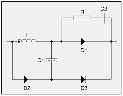
Power factor correction boost designs are now turning towards the silicon carbide (SiC) rectifier. Although it is an additional cost, the expense of using a SiC should be weighed against the manufacturing, board space and component-count benefits, as it can replace a number of discrete components including snubber networks, while also returning a net increase in efficiency.

Fig. 3. Example snubber circuit using seven components three diodes, two capacitors, a resistor and an inductor. These are used to dissipate the power generated by the unwanted reverse current. A single SiC diode may be cheaper.
Taking control
The use of double sided and surface mount manufacturing techniques is now applicable to power supplies, too. The underside of a board makes an ideal home for control functions, although due diligence should still be exercised.
Keeping it cool
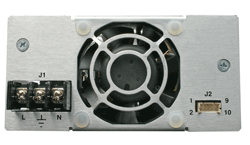
The lifetime of power semiconductors is closely dependent on their temperature. The use of thermally conducting but electrically insulating bonding pads allows direct connection to a heat sink or other substrate. By soldering components instead of using a thermal paste, the thermal bond is much greater. The use of fans in a forced-air cooling design can be improved through a simple control circuit, capable of modulating the fan’s operation based on temperature. This can reduce both the noise generated by the fan as well as the power drawn by it. Incidentally, moving the finger guard a little way back from the fan can significantly reduce audible noise experiment with different types and the spacing between the finger guard and fan to get the best result.

Fig. 4. Finger guard has been pressed outwards slightly to reduce noise.
By using combinations of the above tips, power supply manufacturers can continue to deliver competitive products into the market. In turn, as the industry continues to make improvements to the components available, end-customers also benefit from the resulting design enhancements. ■
Advertisement
Learn more about XP Power


