By Maurizio Di Paolo Emilio, contributing writer
Network traffic is growing at an exponential rate due to the growing popularity of mobile computing devices. As a result, there are continuous rollouts around the world of next-generation wireless standards like 5G. The implementation of higher-level digital solutions with a higher sampling rate is becoming increasingly widespread as digitization becomes cheaper and less power-hungry.
Chip suppliers, therefore, have a huge opportunity, especially radio-frequency (RF) semiconductor manufacturers. Some analysts estimate a 12% compound annual growth rate (CAGR) for base stations and a 5% CAGR for telecommunications backhaul over the next three years. Defense applications also offer excellent opportunities for RF power devices thanks to the industry’s tendency to replace old designs with solid-state devices that exploit gallium arsenide (GaAs) and gallium nitride (GaN) technologies.
MACOM, for example, expects that there will be a 32× to 64× increase in the number of power amplifiers required, which, in turn, could multiply the economic value of this market by more than 3× during a five-year cycle of investment in 5G infrastructure and, according to forecasts, lower the cost per amplifier by 10× to 20×.
5G wireless mobile
The 5th generation (5G) wireless mobile network will run from 24 GHz to 95 GHz and will be able to offer ultra-low latency with a secure and reliable connection. It promises high-speed wireless connections for applications like high-definition 4K/8K streaming TV. This means enormous efforts and pressures for RF and microwave engineers to rapidly design and build 5G and internet of things (IoT) products to compete for a share of the market.
Compared to the previous 3G and 4G LTE implementations, 5G introduces numerous architectural complexities mainly due to the enormous multiple-input multiple-output (MIMO) antenna configurations.
One of the most important tests on millimeter-wave (mmWave) devices is propagation loss. Currently, engineers verify the transceiver’s performance by conducting a series of tests, such as error vector magnitude (EVM), occupied bandwidth (OBW), and spectral emission mask (SEM). To test the antennas, which are integrated on the board or inside the housing, over-the-air (OTA) measurements are used.
Two of the biggest challenges are electromagnetic interference (EMI) and electromagnetic compatibility (EMI), requiring techniques that avoid electromagnetic effects but also total device and equipment failures in mission-critical operations in which heat is a critical design factor.
Beamforming is one of the techniques that can help support the requirements of high speed, low latency, and reliability of the 5G network. Beamforming refers to the most efficient way to create a path between the transmission antenna and the end user, reducing interference and power losses caused by possible obstacles.
It is essential to improve the available output power and energy efficiency of the network infrastructure for these innovative frequency bands by using advanced GaN technology.
RF amplifiers
5G radio equipment must operate in traditional cellular bands and other microwave and mmWave bands, manage complex modulation schemes, demonstrate low energy consumption, and implement new technologies. The base stations are the intersections of cellular networks; they record the transmitted data of a radio cell and transmit them.
To ensure a smooth flow of data across frequency bands in the mmWave range in the future, the output power of base stations must be improved by keeping the energy consumption low, which also reduces the cost of power.
Electronic devices and GaN-based systems are significantly more energy-efficient than conventional silicon (Si). GaN is a material that ensures a high bandgap of 3.4 eV compared with 1.12 eV achieved by an equivalent silicon-based device. A wide bandgap allows the device to support electric fields much higher than the silicon counterpart (of the same size) before a break occurs and, consequently, the device becomes unusable.
The main component of wireless communication systems is the power amplifier in the transmitter. Advanced digital modulation techniques used in high-speed networks require a high-efficiency amplifier to avoid intermodulation distortions that could degrade the signal quality.
There are a variety of amplifier architectures used in the industry to achieve higher efficiency. As an example, the Doherty amplifier architecture guarantees extremely high power efficiency with input signals that have high average peak ratios (high peak-to-average, PAR, or PAPR). Doherty amplifiers are often used in situations when a variable amplitude signal must be linearly amplified.
Another technique called “outphasing” is used by many companies such as Fujitsu and NXP to increase the efficiency of the amplifier. It combines two non-linear RF amplifiers with two different ones that drive signals with different phases.
The design techniques for correct selection of the passive components allow designers to optimize the system for a determined output amplitude, obtaining an efficiency improvement.
Another design factor for RF amplifier designers is envelope tracking, in which the voltage applied to the power amplifier is continuously adjusted to make sure it is operating at maximum power.
Unlike a typical power amplifier in which a DC/DC converter provides a fixed voltage, an envelope-tracking system modulates the connection of the power supply to the amplifier with a high-bandwidth and low-noise waveform, synchronized in real time with the signal envelope. Envelope tracking is an RF power management technology that can improve system efficiency at high levels with signals at any LTE bandwidth (Fig. 1 ).
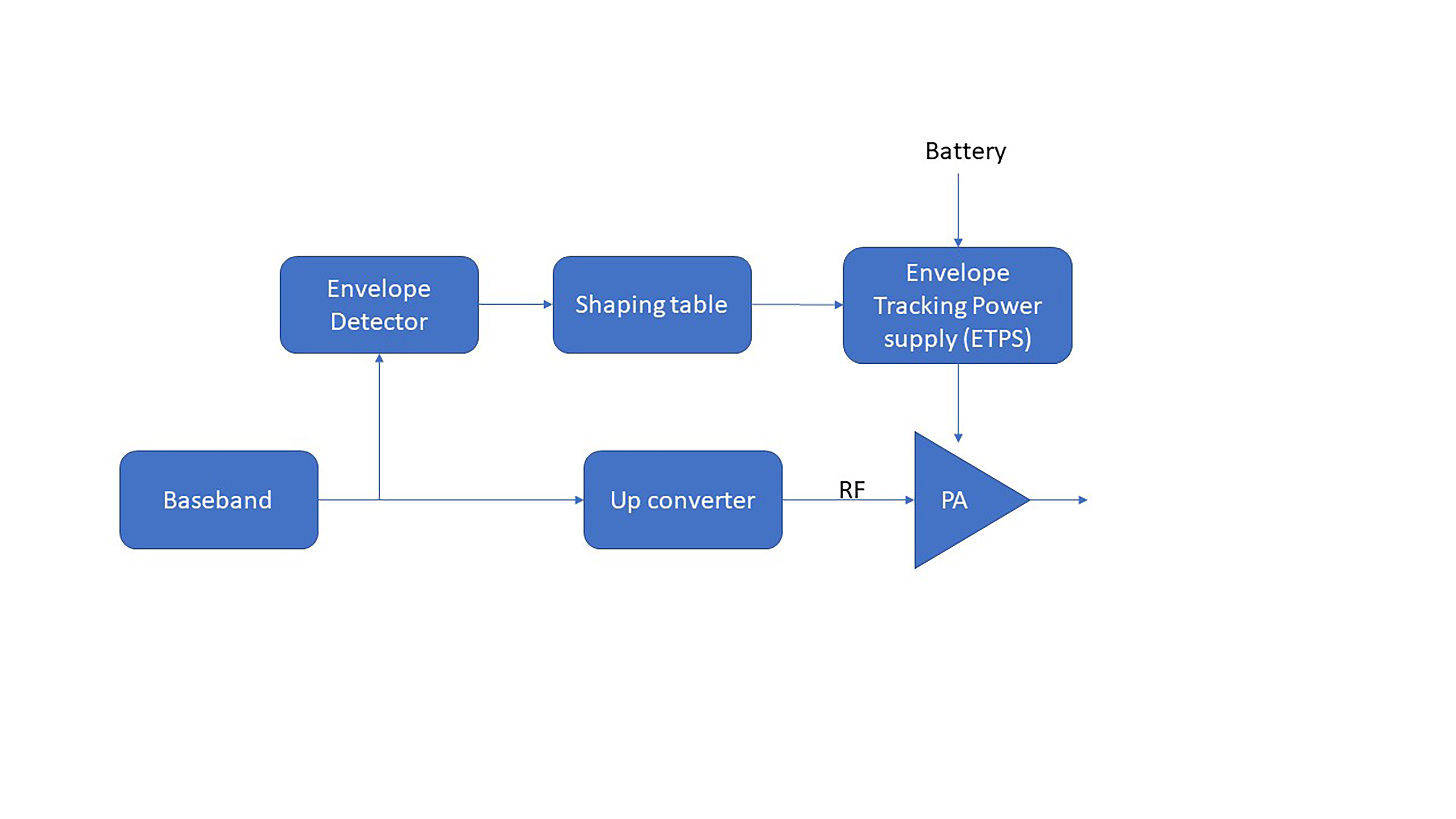
Fig. 1: Block diagram of an envelope tracking amplifier.
With the arrival of GaAs and GaN devices with reduced gate lengths, coupled with new design techniques, new devices are now available that can operate safely up to millimeter wavelengths, opening up new applications that were difficult to contemplate up to 10 years ago (Fig. 2 ).
One example is the MACOM MAAP-011233, a 4-W, four-stage power amplifier assembled in a lead-free, 32-mm AQFN plastic container. This power amplifier operates from 28.5 GHz to 31 GHz and provides 26 dB of linear gain, 4-W saturated output power, and 27.5% efficiency, with 6-V polarization. This product is manufactured using a pHEMT GaAs process that offers full passivation for higher reliability.
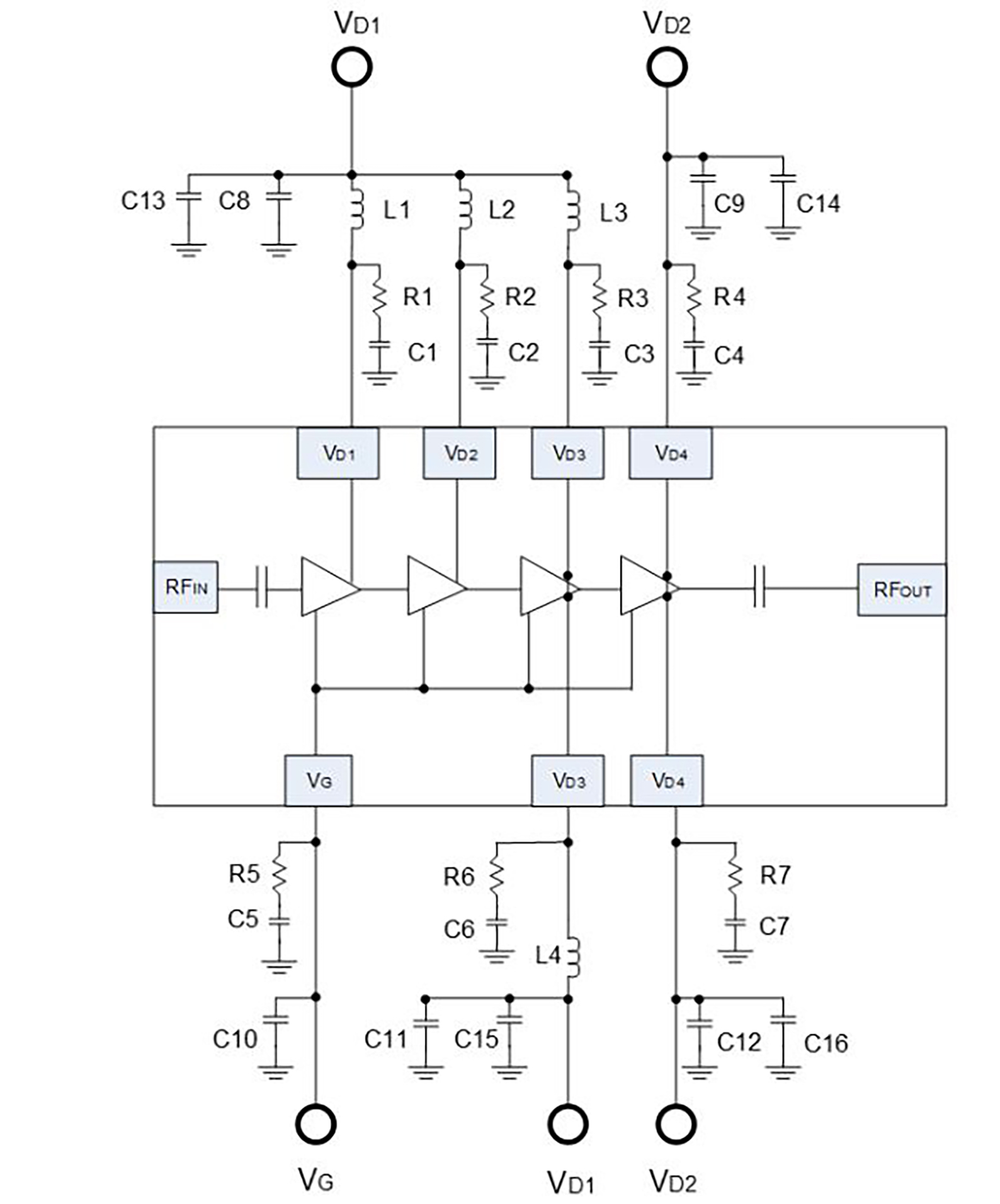
Fig. 2: Application schematic of the MAAP-011233. (Image: MACOM)
Antenna transceiver
RF transceivers are used in many application areas, driven by increased digitalization, massive smartphone adoption, and advanced devices in the telecommunications sector with the advent of 5G. The 5G rollout into a variety of sectors including defense, automotive, and transportation will lead to an enormous market potential for RF transceivers worldwide.
An essential feature for the next 5G base stations is the ability to implement MIMO technology. MIMO uses multiple antennas, each with its own transceiver to transmit multiple data streams in the same bandwidth. This increases the spectral efficiency, which offers higher data rates and greater user capacity.
This has resulted in a higher level of circuit integration for receiver and transceiver chips to achieve lower power consumption and an overall smaller size. In this way, the transceiver chips can be mounted adjacent to the antenna element.
An example is Analog Devices’ ADMV1013 and ADMV1014, a pair of highly integrated microwave upconverter and downconverter. These ICs operate over a wide frequency range with 50-Ω match from 24 GHz to 44 GHz, simplifying the design and reducing the costs to create a single platform capable of covering all 5G millimeter wavelength bands, including 28 GHz and 39 GHz (Fig. 3 ).
The chipset includes voltage variable attenuators, a transmit power amplifier driver (in the upconverter) and a receive low-noise amplifier (LNA) (in the downconverter), LO buffers with a ×4 frequency multiplier, and programmable tracking filters. Most programmable functions are controlled via an SPI serial interface.
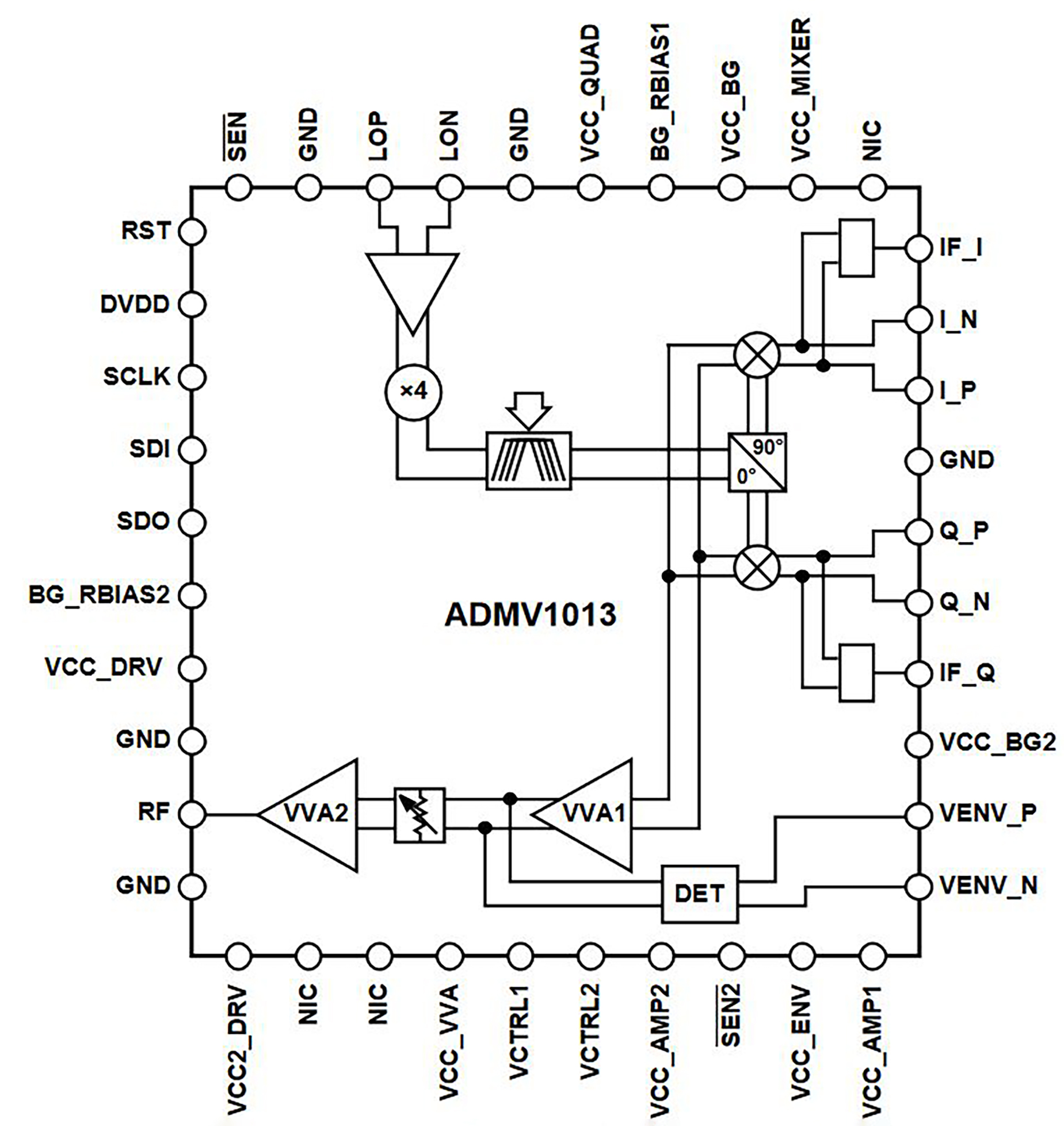
Fig. 3: Functional block diagram of the ADMV1013. (Image: Analog Devices)
Other highly integrated solutions are the AFE7444 and AFE7422 RF-sampling transceivers from Texas Instruments Inc. that can be used in radar, software-defined radio, and wireless 5G applications. Each device can support up to eight antennas and 16 RF bands. Each device integrates four 14-bit analog/digital converters (ADCs) and four 14-bit digital-to-analog converters (DACs). The units can sample 9 giga-samples per second (GSPS) for DAC and up to 3 GSPS for ADC. The direct sampling of input frequencies in the C band is enabled, and the need for further frequency conversion levels is eliminated (Fig. 4 ).
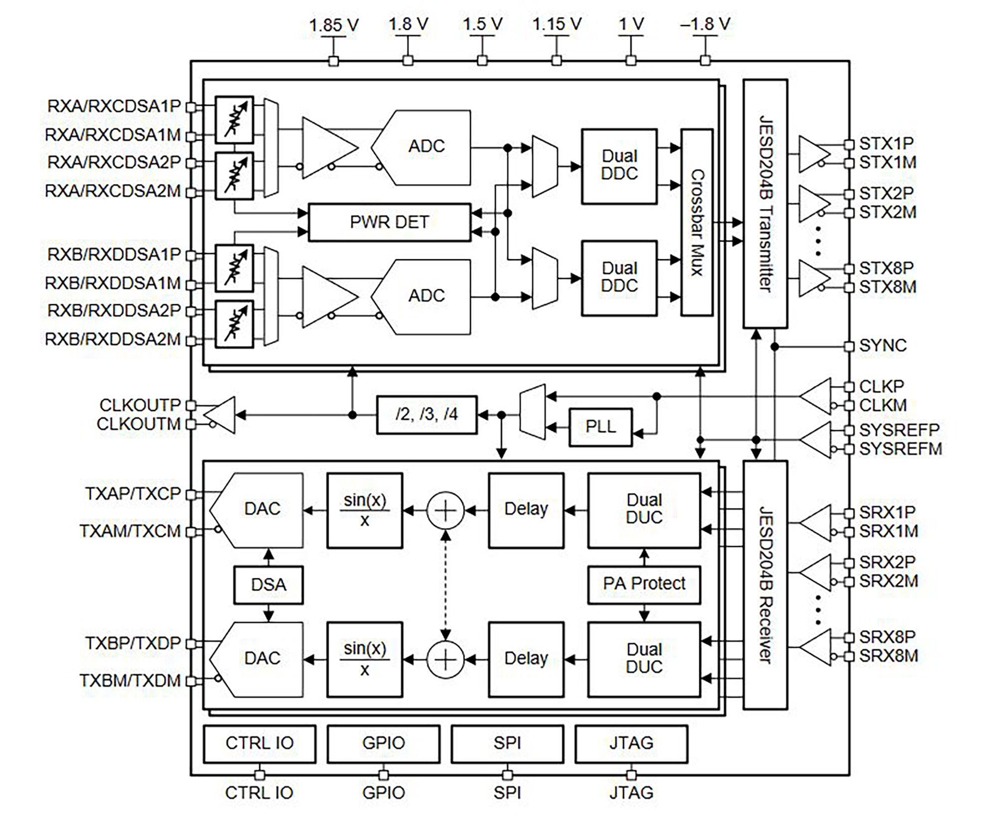
Fig. 4: Functional block diagram of the AFE7444. (Image: Texas Instruments)
Conclusion
For a mobile network to support the high data rates in the smart city of the future, it needs a fast, reactive, and stable protocol capable of handling a large amount of data — it needs 5G! Linearity and energy efficiency in the transmission front end are conflicting requirements that require innovative solutions for present and future mobile systems. GaN technology for power semiconductors has contributed to significantly improved performance levels in RF amplifiers, reducing parasitic elements and, therefore, noise sources.
Advertisement
Learn more about Texas Instruments