BY SPENCER GUO, Application Engineering Manager, TE Circuit Protection, www.te.com/
Lithium-ion (Li-ion) and lithium polymer (LiP) cells are sensitive to fault conditions, such as when over-charge, deep discharge or short circuit conditions create heat and oxygen in a battery application. In this event, the cell being used in the product has the potential to swell, rupture or even ignite. Because these cells are commonly used in tablets, smart phones, ultra-thin laptops and other portable electronics, safety is a primary consideration for electronics manufacturers.
In May 1997, Underwriters Laboratories (UL) published the UL 2054 safety standard for “Household and Commercial Batteries” to help reduce safety risks when batteries or battery packs are used in consumer products. Drawing upon IEC/UL UL60950 Limited Power Source (LPS) Clause 2-5 table 2B, the UL 2054 standard states the requirements of a Limited Power Source, or LPS, test.
This article provides test examples and describes the advantages of using PPTC (polymeric positive thermal coefficient) devices to achieve LPS compliance in Li-ion and LiP battery cell applications.
Evolution of LPS compliance
Battery packs marked LPS are safe for consumers to replace and access, negating the need for specialized electrical technicians to perform basic battery maintenance procedures. Conversely, if the source is not a Limited Power Source, the live voltage on that circuit must be contained in an environment where a tool is needed to access a secured panel. The benefit of an LPS circuit is that connectors and cables connected to the active circuit may require fewer tests and eliminate the need for certification.
Although the first UL edition eliminated most cases of battery-caused catastrophic events, it was found that in cases where the user repeatedly reset the device and reapplied power multiple times without allowing a cooling off or equilibration period, certain loads could staircase in temperature. Over the years, several adjustments have been made to the UL definitions and test requirements to help support the safe proliferation of high-energy density rechargeable batteries.
Two of the revisions in the most recent 2011 edition of UL 2054 (UL 2054 Limited Power Source Test Clause 13 table 13-1(13-2)), address the LPS requirement and the measurement methods for limits for inherently limited power sources. According these revisions, certain end- product devices require that the power output of a battery be limited to reduce the risk a device failure. The LPS test described in Section 13 of UL2054 Second Edition is used to determine whether a cell or battery is suitable in such applications where hazards may otherwise exist.
Approaches for LPS Compliance
UL 2054 Section 13A describes four different approaches that can be followed to meet LPS requirements for batteries, as shown in Table 1 .
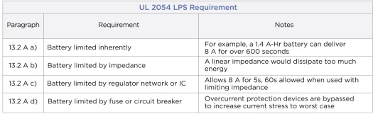
Table 1: The four approaches for meeting the UL 2054 LPS requirements.
A key step in meeting LPS requirements is by testing at the maximum power point load. The value of this load is determined prior to commencement of the tests. To pass the LPS test, the source should be tested under the normal load, at the maximum current load fault condition and at the maximum power load fault condition. For example, the maximum current load used in the following test examples for test cases a, b, and c is an 8.01-A electronic load; 8.01 A is selected to ensure that the current is at 8 A per the requirement of the test.
Figure 1 shows UL 2054 Table 13.1, which lists compliance requirements for cases a, b and c.

Fig. 1: UL’s Table 13.1 for LPS compliance using an overcurrent protection device. (Courtesy of UL.)
Cases a, b, and c require that currents be under 8A, and that apparent power be less than 100 W after a specified amount of time has elapsed. The green highlighted area in Fig. 2 illustrates the acceptable values of current and voltage.

Fig. 2: Limiting voltage and current curve for LPS requirements. (Courtesy of UL.)
Figure 3 shows the UL’s Table 13.2 for case “d”.
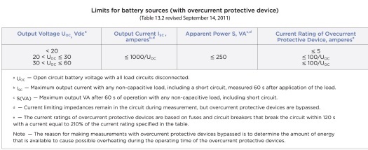
Fig. 3: UL’s Table 13.2 shows case “d” — limiting batter sources with overcurrent protection devices. (Courtesy of UL.)
Test Examples
The following sections show examples of circuits that can help meet the UL 2054 LPS requirements for cases a, b, c and d. The examples for cases b and c illustrate how PPTC devices can be used to help meet the UL’s LPS requirements recommending PTC thermistors on the circuit.
Polymeric positive thermal coefficient, or PPTC, devices are resettable. Unlike traditional single-blow fuses, PPTC devices can reset after a fault is cleared; whereas, when using a fuse, the battery pack becomes disabled if a fuse activates. Additionally, PPTC devices are available in a broad array of current ratings and form factors to help designers’ target specific applications.
13.2 Case “a” — Inherently Limited
A battery that complies with Table 13.2 A for the case “a” (Inherently Limited) requirement must not deliver power that exceeds the limits of Table 13.1 in UL 2054 (shown in Fig. 1). In this example there are no protection devices in the circuit. To determine if the battery is inherently limited, fully charged cells are connected to each of the three loads (normal, maximum power, maximum current), as shown in the schematic in Fig. 4. In each case, the voltage and current are measured and recorded at t = 60 s. If the resulting current and voltage measurement results fall within the green portion of the chart in Fig. 2, the source is inherently limited.

Fig. 4: Case “a”: inherently limited source — without the use of circuit protection devices
13.2 Case “b” — PPTC device
To verify case “b,” the battery is connected with a PPTC device, as shown in Fig. 5. As shown in this example, the load should be set to 8.01A in CC mode and the current, voltage and apparent power should be measured at 5 s. It should then be verified that the results fall in the green portion of the curve shown in Fig. 2. With fully charged cells, the test should be run once with the normal load and once with the maximum power load; and, again, all the results should be confirmed to fall into the green area of the chart in Fig. 2.
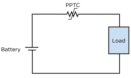
Fig. 5: Case “b”: UL 1434-recognized PPTC device.
13.2 Case “c” — PPTC device and electronic switch
To verify case “c,” the designer can connect the circuit as shown in Figure 6 using a PPTC device and an electronic switch. The load is set to 8.01A in CC mode and the current, voltage and apparent power is measured at 60 s. As with the previous tests, it should be verified that the results fall in the green portion of the curve in Fig. 2. With fully charged cells, the test should be run once with the normal load and once with the maximum power load. Finally, all results should be verified that they fall in the green area on the chart in Fig. 2.
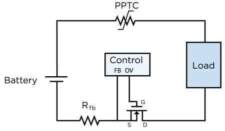
Fig. 6: Case “c”: UL 1434-recognized PPTC device and electronic switch.
13.2 Case “d” — Power Source Limited with Protective Fuse
To verify case “d,” the circuit is connected with a protective fuse, as shown in Fig. 7. The load is set to maximum current (at 210% or 2.10 x fuse current rating) in CC mode and the current, voltage and apparent power is measured at 60 s with the fuse bypassed. The results should be verified to fall in the green portion of the curve in Fig. 2. Using fully charged cells the test should be run once with the normal load and once with the maximum power load. All results should fall within the parameters specified in Table 13.2 (Fig. 3).

Fig. 7: Case “d”: power source limited with protective fuse.
The nuances of the LPS clause of the UL2054 standard can sometimes be difficult to interpret, especially as it relates to the various circuit techniques that can be employed to meet the LPS requirements for systems that do not exceed 20 Vdc. To meet the UL’s LPS requirement for battery safety in consumer products, designers can use PPTC overcurrent devices for two of the four circuit protection approaches to achieve reliable, space saving and flexible designs.
Advertisement
Learn more about TE Circuit Protection Group


