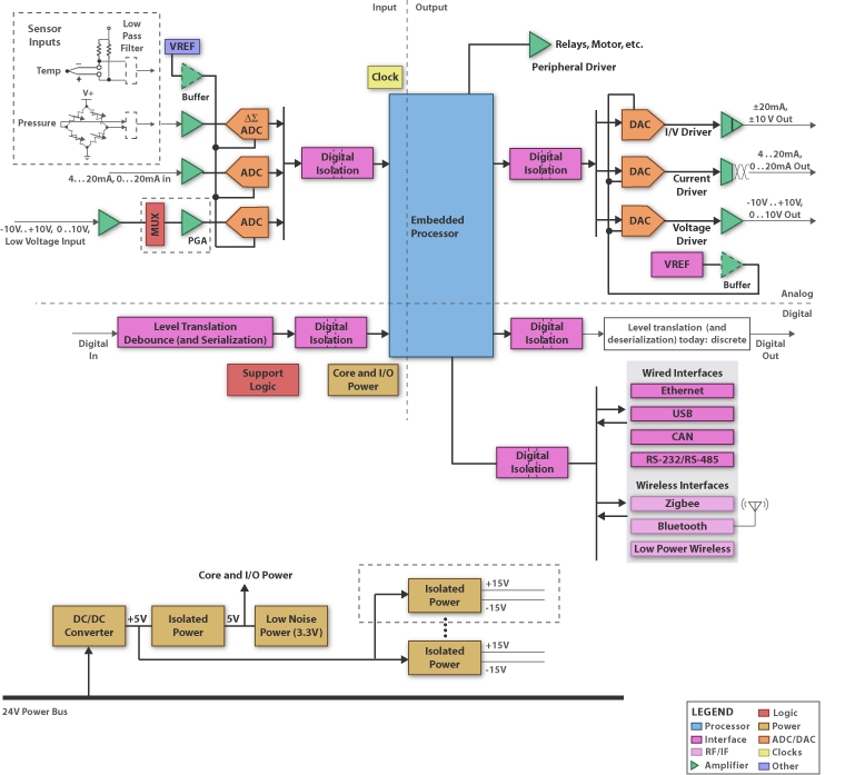
Schematic Block Diagram for Programmable Logic Controllers (PLC)
Programmable Logic Controllers (PLC) and Programmable Automation Controllers (PAC)
are process and control implementations that cover everything from test labs and fabrication plants to military and medical electronics to basic data acquisition. They leverage various sensor types and feedback mechanisms to monitor and control the local environment and system/machine interactions by collecting, storing and analyzing data. Acquiring data from sensors involves precision measurement and the processing of very low values or small changes in analog voltages/currents.
The following general requirements may apply:
• Microcontroller: Contains universal serial interfaces (i.e. I2C and SPI), general purpose I/Os, timers and flash memory. TI offers a range of solutions for the control processor; from the ultra-low power MSP430 microcontroller to the ARM® Cortex™-R4F-based Safety MCUs and C2000 Digital Signal Controllers (DSC) as well as Sitara™ and Integra™ microprocessors. The MSP430F24X family delivers low power consumption, wide supply-voltage range, programmable supply voltage supervisor and an internal reference ADC. 32-bit Digital Signal Controllers like F28235/28335 provide a high level of integration and embedded flash (up to 512kB), ultra fast ADC, communication ports, and a PWM control port. Safety MCUs are built to ease the development and certification of safety critical systems. Safety MCUs 12-bit ADCs, flexible HET Co-Processor and communication peripherals such as USB, Ethernet and CAN enable the MCU to act as a safe networked controller that can perform safe motor control as well.
• Digital to Analog Converter: Low power, output voltage DACs with 12 to 18-bit resolution, sampling rateView Video: DAC9881 Video Cast
• Analog to Digital Converter: SAR ADCs should feature: single supply, 250kSPS, serial interface, 12 to 16-bit resolution, INL• Isolators: The ISO72XX family, which includes one to four channel devices with different configurations and speed grades, are a good fit as a 4kVpeak, 3kVrms is required for safety approval (UL1557, VDE0884). The maximum working operation voltage is 560Vpeak. All inputs should be 5V tolerant.
• Input Amplifier: a bipolar supply, high impedance, and low offset are key for all input amplifiers. For voltage specific use, there should also be wide common mode as in the INA146/148. For current use, low drift and gain>1 as in INA128 is recommended.
• Output Driver: The XTR300 is a complete output driver that not only satisfies the voltage supply requirement of 12V but also the current output requirement of ±20mA. Common driver requirements are: offset 2MHZ. Some members of the XTR1XX family support voltage while others only support current. For additional voltage drivers, see OPA2XX.
• References: If not integrated into the converter, should be 2.5V or 5V with low quiescent current and drift. Many of the REF31XX, REF32XX, and REF50XX devices meet or exceed these requirements.
• Connectivity: Traditional analog (4 – 20mA) and RS-232/RS-485 interfaces remain popular choices for industrial control and sensor applications. Looking forward, designers are integrating mainstream wired interfaces such as Ethernet, USB, and CAN, into their products. In addition, wireless options such as ZigBee, Bluetooth, and other Low Power Wireless protocols are becoming more prevalent. TI is committed to provide solutions for both traditional and emerging industrial interfaces. For example, TI recently introduced the ISO1050, the world's first isolated CAN transceiver.
• Power: DC/DC controllers (e.g. TPS40210) utilize external power MOSFETs for maximum design flexibility. An LDO like TL317 is a simple, inexpensive power regulation and DC/DC converters with integrated power MOSFETs like TPS5410 offer highly integrated step down regulation. For fastest time-to-market solution, consider the DCH0105XXX family as plug-in modules.
Download Full Block Diagram Below
Advertisement

Learn more about Texas Instruments


