Protect Ethernet systems from ESD, other overvoltages
Not all Ethernet installations are the same so different kinds of circuit protection are needed to protect them
BY PHILLIP HAVENS
Littelfuse, Chicago, IL
http://www.littelfuse.com
Ethernet has become the de facto communications method in a growing range of applications—not only in office communications but in industrial networks and even television set-top boxes. Ethernet circuits are exposed to multiple electrical threats, both indoors and outdoors, so they must be protected with appropriate voltage suppression devices. The selection of the right protection devices is far from trivial. This article will explain the kinds of circuit protection needed to protect Ethernet equipment and will provide simple low-cost examples of appropriate methods and circuits.
Not all Ethernet installations are the same; some indoor systems with short cables and no unused ports may be subject only to ESD handling issues, which require only tertiary protection. In contrast, systems that connect buildings located hundreds of feet apart in areas where thunderstorms are common may require considerably greater protection, including both tertiary and secondary protection components. This article will review the concepts and considerations in order.
Data rate
Data rate greatly influences the choice of the type of circuit protection device, because higher data rates use smaller voltage swings and more complex encoding schemes than the lower data rates. Let’s contrast 10Base-T, 100Base-T, and 1000Base-T systems to see this difference:
10Base-T uses a simple Manchester encoding at 10 MHz (11 ns per transition), and the voltage swing is close to 2 V.100Base-T uses a somewhat more complex MLT-3 coding scheme: the receiver must distinguish three voltage levels separated by a single-volt magnitude, and transitions occur every 8 ns. 1000Base-T uses the considerably more complex PAM-5 coding scheme with five signal levels just 500 mV apart, and makes transitions every 8 ns. At these small voltage swings, solid-state type circuit protection devices are the only feasible option. Unfortunately, such devices have a voltage-dependent capacitance characteristic, which means that each of the five signal levels will see a different capacitance value from the protection device. This can cause signal distortion and unrecoverable data errors. The problem becomes worse at elevated temperatures where noise budgets are reduced. The cure for this problem will be discussed in the section titled “Available protective devices.”
Exposure level
The length and location of the cabling used in an Ethernet installation has a substantial effect on the amount of circuit protection required.
Many indoor installations use short cables; in fact, ports with these so-called 2-meter cables face little threat beyond that of someone acquiring a static charge and touching an unterminated cable end or port. This is the basic ESD problem mentioned previously. Tertiary protection is highly recommended in this case. Too often, this exposure is overlooked, running the risk of equipment damage and downtime.
More problematic are long intra-building (indoor) cables, perhaps running from floor to floor within a building or even across a roof. These can accumulate significant electrostatic charges when left disconnected; when plugged back in, they discharge, causing equipment damage. They can also act as antennas for coupling the energy from nearby lightning strikes. In addition, in North America, some parts of Telcordia GR-1089-CORE requirements may apply, depending on the customer’s need for a highly reliable communication link (often touted as the five 9’s).
Ethernet is increasingly being used in exposed areas, including from building to building and other outdoor applications. For example, it is used in what are called “Ethernet in the final/first mile” (EFM) telecom applications. Other areas of high exposure include kiosks, campuses and detached garages. Ethernet is even used for factory automation networks and for a variety of outdoor equipment, including building security cameras mounted on poles in parking lots, and for fiber to the home nodes. Not only are these installations exposed to the full electrical and electromagnetic environment, many of them have little or no temperature control.
PoE applications
Power over Ethernet (PoE) is becoming more popular because it eliminates the need to run separate power wiring to a remote device. Popular applications include terminal equipment, security cameras, mass notification systems for college campuses, voice over IP (VoIP) telephones, kiosks and wireless LAN access points in public places and in private locations such as warehouses.
PoE uses a nominal 48 V (variable from 36 to 57 V) and can provide up to 13 W. There are two wiring options: Mode A, in which power and signal share two wire pairs, and Mode B, in which separate pairs on the Ethernet cable carry power and signals. The pairs float (that is, are not referenced to ground), with the voltage appearing between pairs, as prescribed by IEEE 802.11af. A newer version, PoE+ (specified by IEEE 802.11at), will deliver up to 24 W in which all four wire pairs would be used to ferry power. There are also some nonstandard implementations that require special caution.
Because design engineers will not always know what will be plugged into their equipment, it is best to assume the worst-case condition and design for it; at a minimum, protect assuming a nominal 48 to 72 V for PoE-type systems on all lines.
For more on PoE protection, see “Protecting Power-over-Ethernet Apps”( http://www2.electronicproducts.com/Protecting_Power-over-Ethernet_apps-article-littelfuse-mar2007-html.aspx) in Electronic Products , March 2007.
Driver- vs. line-side protection
Circuit protection devices can be applied on the driver side (tertiary level) or the line side (secondary level) of the transformer, but it can be difficult to know which is best. If the protection is placed on the driver side, then the transformer’s magnetics will limit the energy that will be let through to the protector. In addition, the transformer will greatly limit the common mode energy. What’s more, for tertiary protection, PoE is not an issue.
If the protection is deployed on the line side, then the protector will limit the energy and voltage that can be delivered, which means the transformer can usually be smaller and less expensive, thus saving cost; it may save enough real estate to make up for the protective circuitry. And, in cases in which overcurrent protection is required, the overvoltage protection in a secondary placement protects the transformer winding during power fault events before the overcurrent devices activate.
Available protective devices
As mentioned previously, Ethernet systems are best protected with solid-state semiconductor devices —usually in the form of diode arrays—but the decision to use diode arrays depends heavily on the application.
For low-data-rate, short-distance applications (2m 10Base-T, for example), a light-duty silicon protection array (SPA) with a 2.5A surge rating for tertiary protection will generally be adequate.
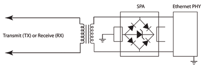
Fig. 1. Recommended protection for 2-m circuits at all data rates.
For medium-duty applications with a higher exposure and more sensitive driver ICs (longer communication links and higher data rates), there are SPAs with 8–A surge ratings, some of which can be doubled up to provide 16–A surge capability in a tertiary position. For the highest data rate links (1000Base-T) in an intra-building application, an SPA with a 150–A surge rating may be needed, but some of these devices can be problematic at high temperatures or where capacitance nonlinearity is important. Under these conditions, it is often better to use overvoltage protectors (OVPs) with 150–A surge ratings that use a biased bridge technology; the bias significantly reduces the device’s voltage-dependent capacitance, and thus helps to eliminate changes to that capacitance with changing line voltages. Similar devices are available with surge ratings to 800–A, and where necessary, some devices can meet GR-1089 requirements without the need to add series resistance.
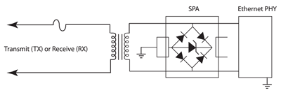
Fig. 2. Recommended protection for GR-1089 10Base-T or 100Base-T intra-building circuits with no PoE.
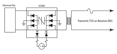
Fig. 3. Recommended protection for GR-1089 1000Base-T intra-building circuits with no PoE.
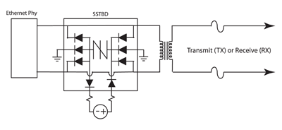
Fig. 4. Recommended protection for GR-1089 intra-building circuits with no PoE.
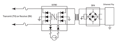
Fig. 5. Recommended protection for GR-1089 inter-building circuits with or without PoE.
It is important to note that a fuse with the appropriate time delay and surge-handling capability is also needed to pass GR-1089 inter-building requirements.
Three key questions
It is generally possible to determine what protection components are appropriate for a particular application by answering three questions:
What is the exposure level? The answer may not be obvious and may require asking the project manager some questions. Is it a 2meter application or will it involve communicating with equipment on another floor or a remote part of the building? Will anything run outdoors or on the roof? Will the equipment be subject to GR-1089? Is Power over Ethernet involved? If not now, is there a chance a PoE system will be attached to the equipment in the future? When people see an RJ45 connector, they tend to plug in cables first and ask questions later. It is generally better to assume PoE will be involved.What is the data rate? Is it a 100Base-TX system? Gig-E (1000Base-T)?
Armed with the answers to the three questions above, the following table provides a good starting point for choosing the appropriate protective device.
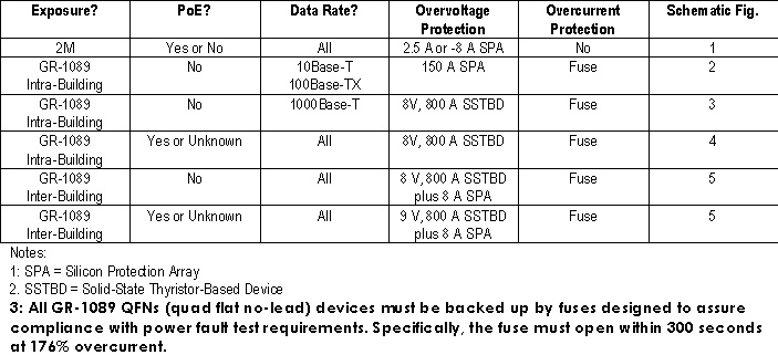
Table. Criteria for selection of protection devices
Suggestions
The suggestions given here should make it possible to implement a cost-effective protection scheme. Keep the following general pointers in mind while developing the design:
When using a biased-bridge suppressor, it is a good idea to connect the bias supply through 1 or 10-MΩ resistors; this will satisfy most isolation requirements.
The bias supplies may be ground referenced or floating, and their voltages should be as high as possible as long as the total differential voltage does not exceed the bridge’s Vdrm (off-state) rating.
Possible bias sources include a 48V battery, the PoE supply, or a 5V processor supply. It is important to note that the bias feed resistors must have a voltage rating higher than the Vs (switching voltage) rating of the bridge to ensure they do not flash over during a surge event. This often requires the use of a 0805 resistor.
The protective device should be placed as close as possible to the point where ESD or lightning-induced events may enter the system.
Advertisement
Learn more about Littelfuse


