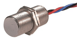
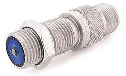
A general overview on the differences between these popular magnetic speed sensors
Quality of a magnetic speed sensor depends on a number of things, including cost, magnet orientation, frequency range, signal bounce, and the design of associated logic circuitry. To say one type is better than the other wouldn’t be a fair assessment. Rather, understanding the differences to all of the many magnetic speed sensors out there will help you decide which kind is best for your particular application.
Reed switch sensor
A reed switch consists of a pair of ferromagnetic blades hermetically sealed in a dry, inert-gas atmosphere at opposite ends of a glass capsule. The reeds are positioned in cantilever form so that their free ends overlap, separated by just a small air gap.

This is referred to as the “Form A” reed switch. Two other common forms of the Reed Switch include: “Form B”, which remains closed in the absence of a magnetic field, and open when a magnetic field is nearby, as well as “Form C,” which has three contacts: a common contact, open contact, and closed contact.
For the purpose of explaining the Reed switch speed sensor, we’ll use the more common “Form A.”
When a magnetic field is generated parallel to the reed switch, the reeds become flux carriers in the magnetic circuit. When the magnetic force exceeds the spring force of the blades, the contacts close, which completes an electrical circuit. Manufacturers assure sound electrical contact by applying a thin layer of non-ferrous precious metal over the contact portions of the reeds. When the magnetic field ceases, the stiffness of the reeds cause them to separate.
The reed switch sensor is stationary while the magnet is attached to a rotating object. The orientation and direction of the rotating magnet determines when and how many times the switch opens and closes per revolution. This number is inputted to a counter and the data used to record speed.
Advantages:
Due to the fact that the reeds are hermetically sealed, the Reed Switch Sensor is suitable for use in explosive atmospheres like, say, where tiny sparks from switches would otherwise be hazardous. Furthermore, the glass enclosure protects the reeds from knocks and exposure to harmful environmental elements.
The Sensor is also immune to electrostatic discharge (ESD) and can withstand higher voltages. It’s capable of directly switching loads, from as low as a few microwatts (without the need for external amplifiers) to as high as 120 W, too.
Disadvantages:
A strong, external magnetic field can disable the Switch. It’s vulnerable to damage from mechanical shock and can experience a change in sensitivity due to mechanical stress. Additionally, the Reed Switch has a limited lifespan: about 3 billion operations of low-power usage.
Uses:
The Reed Switch is used in a wide number of applications, including as a speed sensor on bicycle wheels, car gears, and treadmills. Additionally, the unique design of the Switch allows for the device to be used in other capacities like position sensing, coil applications, and temperature sensing.
Hall-effect speed sensor
The Hall-effect speed sensor is based on the physical principle of the Hall Effect, which was discovered by Edwin Hall in 1879. Essentially, the effect is this: a voltage (also known as the “Hall voltage”) is generated transversely to the current flow direction in an electric conductor when a magnetic field is applied perpendicularly to the conductor.
A Hall-effect speed sensor, in turn, is a noncontact magnetic sensor that records the distortion of the magnetic field, and outputs speed and direction measurement (as opposed to other Sensors which just record the rate of change). This unique capability allows the sensor to detect objects moving at slow speeds, or those moving at zero speed. When keeping tabs of an object’s total revolutions, the ability to record zero speed ensures that you will never lose count, even when the target moves slowly.
Today’s Hall-effect sensors are offered in many different sensitivities, configurations, and output types (linear or digital). What’s important to note about the design of these Sensors is that signal-processing electronics are typically integrated in the same package as the transducer. This means that little or no additional signal-processing circuitry is needed. It also means that the signal from the transducer does not have to travel very far to get to the signal-processing circuitry, which greatly reduces any chance of interference and subsequent malfunction/failure.

Advantages:
Given that the Hall sensor is a noncontact electronic device, there’s no wear and tear from friction. When packaged right, they’re immune to dirt, dust, and water. For these reasons, it’s considered to have a virtually infinite lifespan.
The sensor is capable of measuring large currents and can withstand high-speed operation over 100 kHz. Also, since the voltage isn’t transmitted directly to the Sensor, the safety of the measuring equipment is greatly enhanced.
Disadvantages:
Even though they’re normally positioned within close proximity to the object being measured, it should be noted that Hall Effect Sensors have a limited maximum sensing distance (varies by manufacturer). They have a maximum operating temperature, too. Furthermore, these Sensors are ESD sensitive and magnetic flux from their surroundings (e.g. wires) can render results inaccurate.
Uses:
The Hall Effect Speed Sensor is commonly used to time the speed of wheels and shafts. Examples include internal combustion engine ignition timing, tachometers, and anti-lock braking systems. It’s also used in automotive and industrial electronics (e.g. with a pneumatic cylinder) as well as brushless DC electric motors to detect the position of the permanent magnet.
Variable reluctance sensor
A variable reluctance sensor (VRS) is used to measure the rotational speed of a passing target. So long as it’s positioned nearby, it can convert the mechanical motion of a ferrous actuator, such as a gear or rotor, to electric energy without direct contact. Here’s how:
The VRS consists of a winding wound around a cylindrical magnetic material, typically made of some type of ferrous material. This is referred to as a pole piece. A magnet is attached behind the pole piece, which creates a magnetic field through the piece and winding. The field projects out the pole piece front, referred to as the “sensor tip”, and when ferrous material passes through and disrupts the magnetic field, an electric signal is generated.

The frequency of the recorded signal is directly proportional to the speed of rotation, material being sensed, and distance between the sensor tip and rotating object (also known as the “air gap”). As the ferrous material passes by the face of the magnet, the amount of magnetic flux passing through the magnet and pole varies; that is, when the material is close to the sensor, the flux is at a maximum, and when it’s further away, the flux lessens. This cyclical pulse train can then be fed into a digital counter, totalizer, oscilloscope, or other monitoring and control device to process the signal and get a digital wave form that can be counted and timed.
Several variations of the VR sensor are available today. Options include hermetically sealed, cryogenic, high-temperature, intrinsically safe, explosion proof, and more. This makes them suitable for a wide range of applications.
Advantages:
The VRS is a relatively uncomplicated device that’s accurate, durable, and versatile. It’s self-powered, performs well in harsh environments, and can withstand high-temperature applications. In fact, with appropriate construction, this sensor can operate at temperatures in excess of 300°C!
Disadvantages:
Due to the fact that the magnitude of the signal developed by the VRS is proportional to target speed, it can be difficult to design circuitry that accommodates slower-speed signals. Also, the need for additional processing circuitry offsets the inexpensive cost of the transducer.
Uses:
The VRS is often used as a geartooth speed sensor. It’s also used to sense the turbine speed of jet engines as well as engine cam shaft and crankshaft position control in automobiles due to its ability to withstand higher temperatures.
Summing it all up
In short, no magnetic speed sensor is better than the other. They all have their advantages and disadvantages. Couple that with each technology’s continued advancements and the line that differentiates them becomes even more blurred.
When it comes to deciding which one is right for your application, having a basic understanding of the fundamentals of these technologies helps, but also speaking with the manufacturer about how you plan to utilize the sensor will ensure that you make the right purchase. ■
Related Products: Electromechanical Switches
Advertisement
Learn more about Electronic Products Magazine


