Which type you choose can have a big influence on performance
BY JERRY SEAMS
TT electronics, IRC Advanced Film Div.
Corpus Christi, TX
http://www.irctt.com
Whether your application is a precision voltage reference or an instrumentation amplifier, voltage dividers account for a large percentage of precision resistor applications. Resistive voltage dividers are simple circuits, yet questions and misconceptions still pop up when discussing their design:
• If my system is specified to operate from –55° to 125°C, how much will my output voltage vary from the ideal?
• What happens to the divider output over a range of temperatures?
• My output voltage will be within ±0.1% of ideal if I use ±0.1% resistors, right?
Choosing a method
There are basically two ways to achieve a resistive voltage divider: by connecting two discrete chip resistors at a common point or by using a resistor network with the connection made inside the divider package. Which type you choose can have a big influence on the performance of your divider.
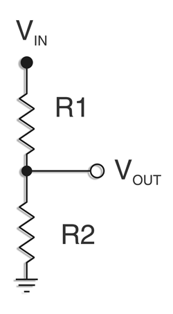
A simple resistive voltage divider consists of two resistors connected in series (see Fig. 1 ). The input voltage is connected to the top of the divider, the output voltage is found at the node between the two resistors, and the reference voltage (usually circuit ground) is connected to the bottom of the divider.

Fig. 1. A simple two-resistor voltage divider.
The divider works according to Ohm’s law: V = IR. If a voltage (VIN ) is applied to the divider input, a current (I) flows through both resistors. Ohm’s law then says there will be a voltage developed across each of the resistors that will be a portion of the input voltage. V1 = I(R1 ), VOUT = I(R2 ) and VIN = V1 +VOUT . The input voltage is “divided” into two voltages.
The transfer function of the divider is found by dividing the output voltage by the input voltage:

The transfer function shows that the output voltage depends on the input voltage and the values of R1 and R2 . In this ideal example, VOUT depends on VIN by exactly the ratio of

and at all temperatures the resistor elements see in operation. But resistors are not ideal. Real resistors have initial tolerance and temperature coefficients that can introduce significant errors into electronic systems.

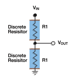
Fig. 2. Voltage divider constructed using discrete chip resistors.
How do these effects contribute to the error of a nonideal voltage divider? Let’s take a look at the effect of initial tolerance on a divider’s output voltage. If the voltage divider consists of two separate resistors (see Fig. 2 ), the output error depends not only on the initial tolerances of the discrete resistors, but also on the ratio of the divider. If R1 = R2 , then the maximum error at the output voltage due to the tolerance of the resistors is equal to the initial tolerance of the resistors. But what about when R1 ≠ R2 ?

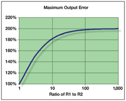
Fig. 3. Divider output error increases as the ratio increases.
When R1 and R2 are different values, the voltage output error approaches two times the initial resistor tolerance as shown in Fig. 3 . The worst case for voltage divider design occurs when the tolerance of one resistor is opposite the other. If the divider is designed with ±0.1% tolerance resistors, the output error may be as bad as ±0.2% at high divider ratios.
Balancing tolerance
Figure 4 illustrates a way to reduce this twofold tolerance error. By depositing and patterning precision thin-film resistors on a single monolithic substrate, the resistor elements have very similar electrical characteristics. Because we are concerned about the “divided” output voltage that depends on the ratio of R1 to R2 , the absolute tolerance of each resistor element is irrelevant. By purchasing a thin-film resistor divider with a ratio tolerance of ±0.1%, we are assured of a maximum output error of ±0.1% due to initial tolerance regardless of the tolerance of each individual resistor — twice as good as the discrete solution.

Fig. 4. Voltage divider constructed using thin film on a monolithic substrate.
Not only does the idea of using a monolithic thin-film voltage divider make sense for reducing output error due to tolerance effects, it has similar benefits for reducing error over temperature as well. Typical precision chips have ±25 ppm/°C temperature coefficients (TCRs). This means that each resistor can change by as much as ±0.25% if the resistor temperature reaches 125°C (100° above room temperature). The output voltage can have an error as high as two times this (or ±0.5%) if the temperature coefficients of R1 and R2 move in opposite directions.
Conventional thin-film voltage dividers have TCR tracking between the two resistor elements of ±5 ppm/°C. Again, because the thin-film resistor elements are deposited and processed identically on a monolithic substrate, they move together over temperature. And again, because the ratio of the two resistor elements is important to the output voltage, the absolute temperature coefficient of each resistor element is irrelevant to the accuracy of the divider. By purchasing a thin-film divider with a ±5 ppm/°C TCR tracking spec, the output voltage error due to temperature effects is reduced over the 100°C span from ±0.5% to ±0.05%; a tenfold improvement.
The table summarizes the two approaches. When designing a voltage divider using 0.1% discrete resistors, the maximum output error due to tolerance and TCR is 0.7%. The maximum output error when using precision thin-film resistors is ±0.15% — more than a fourfold improvement in performance.
It is tempting to assume that a divider output voltage will be within the tolerances of the resistors chosen to construct the divider. Further investigation reveals that the expected output voltage is affected by the ratio of the resistors in the divider as well as their initial tolerances and temperature coefficients.
By selecting a precision thin-film voltage divider on a monolithic substrate the designer ensures that the resistor elements in the divider have very similar electrical properties and will track well over temperature and time. The similarity of materials and processing on a common substrate promises a more stable and better-performing voltage divider over all ratios and environments. ■
| Comparing voltage dividers | |||||
| Tolerance | Tolerance Output Error | TCR | TCR Output Error (100C span) | Total Output Error | |
| Discrete Chips | ±0.1% absolute | ±0.2% | ±25 ppm/C absolute | ±0.5% | ±0.7% |
| Monolithic Divider | ±0.1% ratio | ±0.1% | ±5 ppm/C tracking | ±0.05% | ±0.15% |
Advertisement
Learn more about TT electronics IRC


