Smaller and higher density electronics are an ongoing trend. These increasingly integrated and complex designs, however, are now much more sensitive and vulnerable to damage and downtime from transient threats such as lightning and other high voltage surges. With the varied nature of telecommunications, industrial, and medical equipment designs, a single device surge protection solution is seldom possible. A multi-stage/multi-technology protection approach is required to take advantage of each technology’s strengths and weaknesses.
Comparing overvoltage protection
Overvoltage devices divert fast surge energy such as lightning, while most overcurrent devices increase in resistance to limit the surge current flowing from longer duration surge currents. There are two types of voltage limiting protectors: switching devices like GDTs that crowbar the line and clamping devices such as MOV and TVSs (see table). GDTs have gained popularity due to their extremely low capacitance and low leakage characteristics, along with their high surge current handling capabilities.
| Technology | Overvoltage Type | Pros | Cons |
| Gas Discharge Tube (GDT) |
Crow-Bar |
High Surge Current Handling Very Low leakage Very low |
Slower response time (µs) Size-Packaging Poor ability to protect to low voltage levels
|
| Metal Oxide Varistor |
Clamp |
High Surge Current Handling Fast Response time (ns)
|
Higher Leakage over time High capacitance Size & packaging of high current devices |
| Transient Voltage Suppressor (TVS) |
Clamp |
High Surge Handling Fast Response time (ns) Medium Surge Current handling Capable of protecting to low levels |
Higher capacitance Current handling capable with larger size
|
Typically placed in a circuit to limit voltage and to divert surge current to ground (common mode) or to a source (differential mode), a GDT has very high impedance (>1 GΩ), so it is virtually invisible to the circuit during normal operation. When a voltage disturbance exceeds the GDT’s sparkover value it will switch into a virtual short circuit, known as arc mode, diverting the surge current and protecting the equipment. GDTs typically have a fairly slow response time due the time needed to ionize gas inside the GDT. Conventional GDT devices provide robust overvoltage protection, but they do so at the cost of valuable PCB space.
Effective protection using a three-stage solution
Designers can use an advanced three-stage protection solution for high density designs. This employs TVS diodes for secondary protection, high-speed protector (HSP) devices for coordination, and GDTs for primary protection and is optimal for applications located in exposed transient environments. It offers a coordinated response to provide a high level of protection for various telecom or industrial interfaces that far exceeds the handling capability of a single-stage component solution.
A TVS diode alone is effective for low level transients. It will camp transient signals up to its peak impulse current, but cannot handle above that. As the incident transient voltage to which the TVS diode is exposed increases, so does concern for exceeding the current limitation. Using series resistance to protect the TVS can result in excessive voltage drop and, in the case of communications, can greatly reduce loop distance.
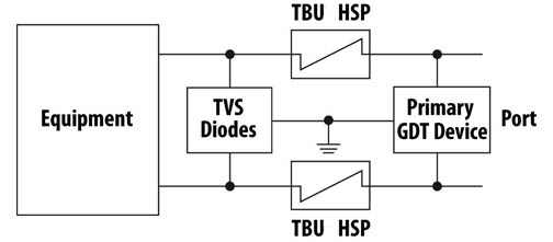
Fig 1: Maximizing HV transient protection needs a three-stage design.
HSPs are constructed using MOSFET semiconductor technology. When placed in series between the GDT and TVS, the HSP monitors the current flowing through the line. If the current exceeds a pre-set level, the device triggers and provides a barrier to high voltages and currents. Trigger currents from 150 to 500 ma are available and peak impulse voltage withstand is 650 to 850 V. HSP devices from Bourns are called the TBU-DT Series. They are a resettable device which operates in approximately 1 μs. Normal series resistance is 5 to 10 Ω. When operated, the device restricts line current to less than 1 mA, typically.
When exposed to a fast rising transient event, the faster TVS diode will begin to clamp first and conduct current through the HSP. Once the HSP’s current threshold is exceeded, it operates to protect the TVS diode and downstream components. It also allows the GDT to trigger and take the bulk of the current generated by the surge event. The result is an extremely fast protection that removes the deficiencies of individual protection technologies.
Design engineers can leverage this solution to increase surge and transient protection levels – the HSP limits the let-through energy, the TVS diode keeps the signal within the maximum limits, and a primary GDT protects the HSP device from exposure to excessive transient voltage.
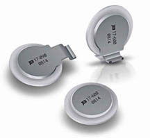
Fig. 2: The Bourns FLAT low profile GTD devices.
Robust protection for space-constrained designs
As equipment shrinks space limitations on the PCB increase. GDT’s normally come in 8 mm diameter cylindrical packages. Recently, a new design for primary GDT protection featuring a flat disk package has become available. The Bourns FLAT GDTs deliver a 75% savings in volume compared to standard 8 mm devices and come in horizontal or vertical mounting versions (Fig. 2). The 2-electrode devices come in five versions with 90 to 420 V DC sparkover and are rated for 10,000 Arms for 8/20 μs for greater than ten operations.
Advertisement
Learn more about Bourns


