Runtime measurements for a hybrid power source
Here’s how a hybrid battery works and why it might be right for your portable application
BY GARRY ELDER
Texas Instruments
Dallas, TX
http://www.ti.com
The demand for longer run time in portable applications is driving the emergence of fuel cells as a new power source in this end equipment space. However, there are still challenges to overcome with a “fuel-cell-only” approach in portable power applications. One solution is to make the power source a hybrid.
Integrating a fuel cell with a battery, supercapacitor, or other power storage device as a combined power source solves several dynamic power supply and thermal issues. However, it generates power management issues of its own.
The hybrid power source
In the following architecture discussions, the hybrid system is defined as a combination of a fuel cell and a battery. That holds true for a variety of fuel cell and battery types, or replacements such as ultracapacitors or supercapacitors. However, each complete solution is tailored to meet the unique needs of the chosen fuel cell and battery.
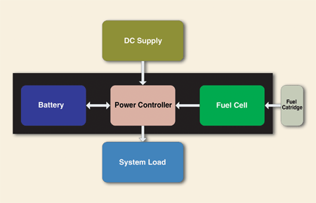
Key system elements of the hybrid include the fuel cell, fuel cartridge, battery, system load, dc input supply, and power controller (see Fig. 1 ). The combined fuel cell and battery is labeled as a hybrid power source (HPS).

Fig. 1. A Power system using a hybrid power source.
The above system, at various stages of use, can provide three energy sources and two loads. When the system is not plugged into a dc supply, a combination of the fuel cell and/or the battery can provide power to the system load. Also, when the dc supply is not present, the battery could also be charged by the fuel cell to maximize end-of-power-shutdown capability or enable better dynamic power response to the system. When the dc supply is available, it provides energy to both charge the battery and power the system load.
With this level of complexity, the system’s power path management must be precisely controlled to ensure the system load can always run to meet the end users demands on it. The most critical time is when the amount of available energy reaches a level where, under certain conditions, it can no longer power the system load and a limited-use configuration is initiated or even a controlled shutdown is performed.
To enable this precision control the power controller needs to be able to sense many factors to generate the key values of peak available energy and total available energy. These key values definitions are as follows:
Peak available energy can be defined as the amount of energy that can be sourced from the hybrid power source over a given short time, maybe a DVD startup or shutdown save to disk operation. The peak period will be based on the end equipment load profile.Total available energy can be defined as the total energy available from the hybrid power source, regardless of discharge rate.
Monitoring the system
The battery can be monitored by a standard fuel gauge readily available in the market today such as the bq20z75 for two, three, or four series Li-ion cell configurations, or the bq27210 for single series Li-ion cell solutions. These solutions provide data based on voltage, current, temperature, and state-of-charge needed, as a minimum, by the power controller.
The battery-monitoring solution interfaces with the power controller via a data bus such as I2C, SMBus, or HDQ. This allows the power controller to have very accurate data on the state of charge (SOC) of the battery and to ensure safe use of the battery during charging and discharging.
Monitoring the fuel cell and fuel cartridge is a little more challenging. The type and quantity of fuel available in the fuel cartridge, along with the present and average efficiency of the fuel cell, needs to be factored into the available energy from the fuel cell.
In many instances, the fuel cartridge is unique to the system so the type of fuel can be stored in the power controller. In other solutions it may be beneficial to have the data for fuel stored with the fuel cartridge and provided to the power controller via a similar interface bus as the battery monitoring system.
In solutions where the fuel cartridge has the capability to store data, it would be ideal to allow the power controller and possible refueling system to write back to the fuel cartridge the measured remaining fuel level. Although this would only be useful for systems where a fuel cartridge can be removed and reinserted.
Other than the fuel cartridge fuel level, there are other parameters that need to be monitored regarding the fuel cell. These include temperature, fuel input rate, voltage output, and current output. These are used to calculate the present efficiency of the fuel cell. Using temperature you can determine if the fuel cell is running in an optimal state.
The dc supply and system-load power data also should be measured to complete the data set. With this data and that from both of the monitoring subsystems, the values for total available energy and peak available energy can be generated. The available runtime of the end equipment is a function of these four factors.
The nature of the fuel cell power output response capability and the battery size also raises a problem when it comes to the end of power shutdown. This needs additional understanding.
Predicting HPS run time
The battery and fuel-cell-monitoring subsystems can provide total and peak energy to the host system, and allow the host system to determine the various pieces of user data that it requires. In this example architecture we have a power controller that can provide several advantages. The main one is that it can manage the data and subsystems, enabling the hybrid power source to be used as if it were any other standard battery power source.
The power controller takes the monitored data and manages the use of the battery, maximizing its capabilities over the expected lifetime of the HPS. This can be beneficial in two specific areas:
Ensuring that peak available energy is at an optimal level by allowing the fuel cell to charge the battery, even when no dc supply is present.
Managing the state-of-charge (SOC) battery so that it has maximum usability within this architecture.
Managing the SOC is a major departure from how a battery is used in most portable applications today. Typically the battery is the only wireless power source, so it has to provide all the power to the host system. Therefore, it needs to store as much energy as it safely can. This provides the ultimate goal of the longest run time. Also, battery charging time is important the shorter the better!
Tradeoffs can be made with charge time, peak SOC, and longevity of the battery. But these are not common in today’s consumer applications. These two usage dynamics don’t apply when it comes to the HPS, so a better balance between the optimal states of the battery and fuel cell can be achieved by using the power controller. Ideally, the battery in a HPS will last for the lifetime of the HPS without needing to be replace. To achieve this goal the power controller can enable battery charge management options such as charging at lower voltages, charging at slower rates, and temperature compensation of the charge voltage/rate. The power controller can ensure also that the system load has enough power from the dc supply when it is connected by regulating the battery charging current.
The recent smart battery data set (SBDS) addendum adding fuel cell data to the existing data set that supports batteries, allows the host to access data that enables it to control the use of the fuel cell and the battery. The use of the power controller can handle the complexity of the HPS and enable the SBDS fuel cell additions to assist the host system to use the HPS more effectively.
The simple addition of total available energy from the fuel cell and battery can provide a basic level of functionality to the host system to indicate available run time, remaining time alarm (RTA), or remaining capacity/energy alarm (RCA).
An equation for predicting runtime is as follows:
AtRateTimeToEmpty (ARTTE) = Total Available Energy / AtRate( )
This equation allows the host system to determine the available run time based on what the host system knows about what the user is trying to do, for example, play a DVD, or run a system diagnostic. It is only beneficial if the host system has information about the energy it uses in different modes and for different programs.
Controlled shutdown and maximized HPS run time
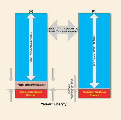
Predicting runtime for the user is a “crystal ball” approach as the future is hard to predict. However, the data provided can be used for enabling a controlled system shutdown when power is low. The more accurate the function is, the longer the system run time.


Fig. 2. Energy usage comparison.
Advertisement
Learn more about Texas Instruments


