Find out what the most common battery-charging faults are that pose safety issues to the device and end users
BY: MIN XU
Technical Marketing Engineer
Monolithic Power Systems
www.monolithicpower.com
Lithium batteries—such as lithium ion (Li+), lithium-iron phosphate (LiFePO4), and lithium polymer (LiPo)—have gained greater market traction in portable battery-powered devices thanks to their greater energy densities, larger number of charging cycles, and lower energy dissipation rate than other common rechargeable battery technologies, including nickel-metal hydride (NiMH) and nickel cadmium (NiCd). However, the technology poses significant challenges to electronics designers. One issue stems from a lack of substantive standardization across lithium battery designs. Another issue stems from lithium-based technologies requiring more-precise charging than older rechargeable battery technologies. The biggest concern for electronics designers are the safety risks associated with lithium batteries because they are more likely than NiMH or NiCd batteries to leak, catch fire, or explode, if improperly charged. This article discusses some of the most common battery-charging faults that pose safety issues to both the device and to the end users.
Common charging faults
Many charging faults can damage either the battery or the devices by allowing voltage or current levels to reach inappropriate levels that either can thermally or electrically damage semiconductors, or compromise the battery’s chemical stability. The following table summarizes these common faults, their causes, describes the type of damage they cause to either the device or the battery.
Many of these faults stem from charging circuits that have direct paths from the adapter to the charging IC, battery, and system. Figure 1 shows a circuit with the aforementioned direct paths: the charger directly connects to the adapter, the system directly connects to the adapter when switch S1 closes, and the battery directly connects to the adapter if S1 and S2 close at the same time.
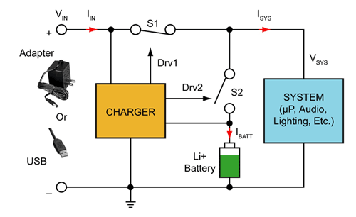
Fig. 1: A common charging circuit without fault protections (simplified).
Fault solutions
There are solutions to the faults described in Table 1 . The following describes these solutions in details.
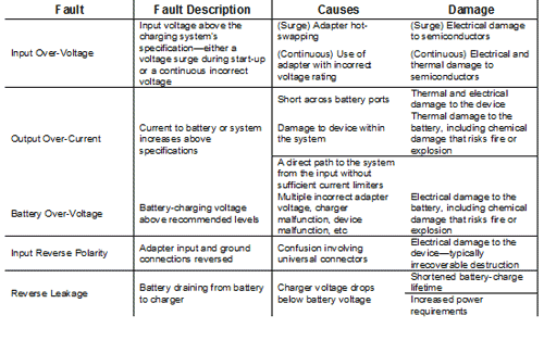
Table 1: List of common charging faults
Input overvoltage
Resolving input overvoltage involves an external protection circuit that with an input overvoltage protection (INOVP) threshold (see Fig. 2 ). If the adapter input voltage exceeds this threshold, the protection circuit blocks the voltage to the charging system for at some period called the immunity time to block voltage surges. If the adapter input voltage remains above the threshold beyond the immunity time, the protection circuit blocks the input under the assumption that the circuit is connected to an adapter with an incorrect voltage rating.
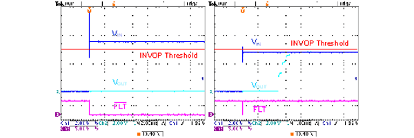
Fig. 2: VIN > INOVP threshold and VIN
Output overcurrent
An output overcurrent condition can occur randomly. As a result, any overcurrent protection (OCP) circuit must constantly monitor the adapter current for current levels using a control method similar to INOVP: if the current level rises above the overcurrent threshold, latch-off the current (see Fig. 3 ). However, if the current only experiences a momentary spike, then keeping the current latched off unnecessarily disables the adapter. Therefore, if the protection circuit cycles between allowing the adapter retry and then checking if the current continues to exceed the overcurrent threshold, then a minor current issue can resolve itself while limiting system, battery, and charger damage. Often, a protection circuit will allow for a certain number of retries before latching off completely.
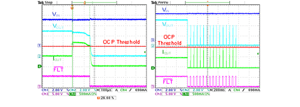
Fig. 3: IOUT>OCP threshold at 100 µs/div and 200 ms/div. Note that the system allows for up to 16 tries before latching off.
Battery overvoltage
Battery overvoltage protection (BOVP) requires monitoring the battery voltage directly, and disconnecting the power source when the battery voltage exceeds some threshold. Similar to OCP, BOVP allows the voltage to resume after some latch-off period to determine if a voltage spike triggered the BOVP (see Fig. 4 ), or if some regulator has malfunctioned the device latches off after a certain number of retries.
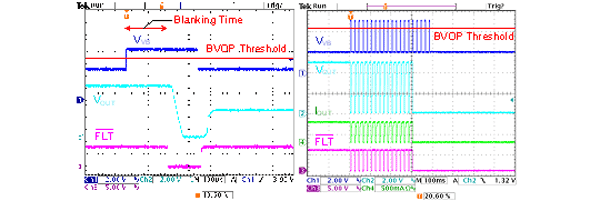
Fig. 4: VVB>BOVP.
Input reverse polarity
Add a diode or a MOSFET between the adapter and the rest of the system (preferably before any protection IC) to prevent a reverse current.
Reverse leakage
Add a diode between the charger and the battery to prevent any reverse leakage.
Charger protectors
Implementing solutions for either input reverse polarity or reverse leakage involves little more than adding a diode or a MOSFET as appropriate. However, implementing INOVP, OCP, or BOVP requires adding circuits that actively monitor and rectify a particular fault (see Fig. 5 ): The most cost-effective and compact solutions use charger protection ICs and inserting them between the adapter and the rest of the system.
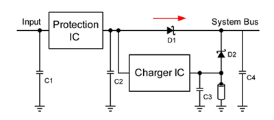
Fig. 5: Charger system with protection IC.
The Monolithic Power Systems MP267x family of charger protectors integrate INOVP, OCP, and BOVP into single ICs, and provide binary counters for both OCP and BOVP to latch off the current or voltage to the charging system after 16 retries. The following plots show the MP2674’s response to INOVP, OCP, and BOVP. ■
Advertisement
Learn more about Monolithic Power Systems


