BY CHRIS CLEARMAN, Motor Control Marketing
Texas Instruments
www.ti.com
Along with the multi-kilowatt ac traction motor that electric vehicles (EVs) use for propulsion are many other auxiliary motors that need to be driven efficiently, precisely, quietly, and reliably. However, many suppliers are used to belt-driven or hydraulic drive systems, and still others are considering bringing the design of these auxiliary systems in-house.
However, it’s not that simple: Driving these motors requires innovative approaches to motor-position sensing and drive algorithms, as well as the careful selection of drive circuitry and components (Fig. 1 ).
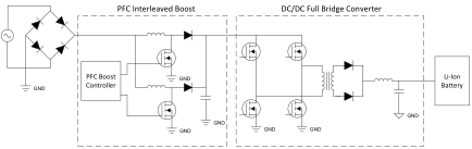
Fig. 1: EV motors require innovative approaches to motor-position sensing and drive algorithms, as well as the careful selection of drive circuitry and components.
Auxiliary motors are used to run supporting functions in a vehicle and have historically been driven off of a belt with energy from the internal combustion engine or the hydraulic system. But in modern EVs, AC compressors, fluid pumps, fans, blowers, turbos, and even specialized tools on farm equipment or forklifts need to run from an electric motor (Fig. 2 ). Most of these applications are quite similar in nature. They typically comprise a low-voltage bus (12, 24, or 48 V) and low-to-medium current (

Fig. 2: The main motor in EVs tends to get all of the attention, but there are many other auxiliary motors that need to be driven efficiently, precisely, quietly, and reliably.
The motor is used to control variable speeds or torques under varying loads. While some may still use Hall-effect sensors for commutation for historical reasons, almost all are in applications that don’t require a sensor — if the developer has the proper hardware and software expertise.
MOSFETs: the critical drive component
MOSFETs are the components used to energize each phase of the motor in a three-phase inverter system. Due to the high-threshold voltage and high amount of capacitance that is parasitic to the FET (typically >100 pF), a driver IC (a gate driver) must be used to drive the gate of the MOSFETs. Modern gate drivers for auxiliary three-phase motor systems integrate many features important to the overall system’s reliability and performance. These are based on protection, configurability, build of material/board size reduction, and motor-control performance.
Because MOSFETs are the key components energizing the three phases, they are the most critical to be protected. Industry-leading gate drivers available today should offer multiple layers of protection for the overall system by having integrated Vds and Vgs monitoring of the external FETs, on-chip thermal measurement, integrated current shunt amplifiers to monitor current flow, power supply monitoring for under- and over-voltage, and shoot-through protection.
Motor-drive waveform considerations
The switching of the three-phase inverter needs to be controlled by digital logic, typically a programmable microcontroller (MCU), to regulate the torque or velocity of the motor while maximizing the efficiency. Using Hall-effect sensors on the motor makes it reasonably straightforward to control a brushless DC (BLDC) motor using a six-step (trapezoidal) commutation control technique with limited digital logic resources, like a very small MCU or even a hard-coded ASIC.
This six-step approach has some limitations surrounding torque inefficiency:
- The six-step trapezoidal switching produces stator magnetic fields in only one of six orientations, whereas the motor efficiency would be maximized if the stator magnetic field could be created in a specific synchronized orientation to the constantly moving rotor magnetic field.
- The switching between these six states causes ripple — a momentary reduction and then correction — of the motor’s torque. This affects the quality of the velocity control and impacts audible noise.
- Dynamic performance (ability to adjust torque creation to meet the instantaneous load requirements) is then affected.
- Efficiency is further reduced in motors wound to produce sinusoidal back-EMF voltage; most motors run more efficiently and effectively when driven with sinewaves instead of square waves.
For very simple EV motor applications, the BLDC approach may be good enough. But for others, these limitations can be crippling; an approach that works better for most of these motors is called field-oriented control (FOC). In FOC, a stator field is produced that is oriented and synchronized to the rotor field, which maximizes torque production. The transition between stator states is smooth, removing torque ripple and improving the dynamic performance of the system. The voltages seen by the motor phases are sinusoidal, enhancing efficiency. FOC isn’t that much more complex than six-step BLDC; it measures at least two phase currents instead of one bus current, it does additional math calculations, an extra proportional-integral (PI) controller is employed, and a few more calculations are made for the pulse-width modulation (PWM) generation.
However, there is the issue of the rotor sensor. The Hall sensors used in six-step BLDCs do not provide enough accuracy on the position of the rotor magnetic field location for FOC. Additionally, Hall sensors have more upfront and lifetime costs due to their low reliability and high system failure rate. Additionally, some applications simply can’t use Hall sensors due to mechanical limitations.
A solution could be to use a different type of rotor magnetic sensor. Both the digital encoders used in high-precision servo drives and the analog resolvers used for the EV propulsion motor have the resolution required for FOC. However, they are expensive and impractical compared to simple Hall sensors. Or, they are impossible to install due to mechanical limitations. The only solution then is sensorless FOC.
Sensorless FOC made practical
Sensorless FOC relies on software algorithms to estimate the rotor magnetic field position based on the currents and/or voltages in the inverter. Sensorless rotor-position estimators have been theorized, developed, and put in use for over 25 years, but their practical implementations have been constrained to those companies with extensive investment in developing the required expertise. Such companies have a strong background in ac drives, industrial motor control, some advanced appliance, and automotive. This expertise has been a prerequisite because the algorithms and controller tuning are difficult to get working in a real-world environment under real-world conditions.
A unique approach that is broadening the adoption of sensorless FOC in EVs and beyond is InstaSPIN-FOC. This employs an innovative self-tuning algorithm that instantly provides robust sensorless FOC of any three-phase motor.
This motor-control technology enables EV designers — even those with limited motor control experience — to identify, tune, and fully control any type of three-phase, variable speed, sensorless, synchronous, or asynchronous motor control system in their EV application in just minutes.
Conclusion
The EV’s main propulsion motor is complemented by a wide range of auxiliary motors that need efficient, low-cost, small-footprint drive schemes developed with attention to reliability, noise and precision. This has pushed the development of advanced algorithms to overcome some of the limitations of classic BLDC motors. As a result, sensorless FOC is emerging as a solution to EV motor drive requirements, but it needs to be readily adaptable by suppliers still moving from the belt or hydraulic drive systems.
This article was adapted from a recent blog series on TI’s Motor Drive & Control blog.
Advertisement
Learn more about Texas Instruments


