By JIA WEI
Marketing and Applications Engineering Director for Mobile Power Products
Intersil
www.intersil.com
When Apple unveiled their new MacBook in early 2015, it opened a new era in power management for computing devices. The 12-in. MacBook features a USB-C port that delivers bi-directional data and power at the same time. This technology eliminated the MacBook’s MagSafe charging port by integrating the charging function into the USB-C port.
Now, a new generation of Intel-based ultrabooks, tablets, and 2-in-1 computers will be launching with USB-C ports in 2016. However, before computer manufacturers rush to market, system designers should understand that USB-C charging requires a fundamental change to their existing power delivery architecture and presents a new set of challenges.
This article examines the traditional PC power architecture and describes how it changes with the adoption of USB-C power delivery using reversible USB Type-C cable connectors. We’ll take a look at different battery charging approaches and explain how a USB-C buck-boost charging topology can provide the flexibility, high efficiency and small solution size to satisfy the designer’s requirements.
Power delivery today
Charging electronic devices through a USB-A/B port is common in today’s low-power smartphones and tablets. The traditional USB-A/B port delivers a 5-V power supply with up to 2-A current capability. However, this power level is insufficient for charging a high-power device, which is typically charged through an AC power adapter with up to a 60-W rating.
Today’s typical computing power architecture includes an ac power adapter that converts ac voltage to a dc voltage and uses 20 V to charge the main electronic device, which could be an ultrabook or notebook computer. They may use different battery cell stacks ranging from a 1-cell battery to 4-cell batteries. Each Li-on battery has a typical operating voltage range of 2.5 to 4.3 V, from discharged status to fully charged status. Therefore, the computer may have a battery voltage range of 2.5 to 17.2 V.
With a 20-V dc-adapter, the battery charger would use a so-called buck topology to step down the 20V DC to charge the battery. The computer’s 5-V USB-A/B port is capable of charging an external USB device, such as a smartphone, tablet, printer or hard drive. To generate the 5 V in the USB-A/B port, the computer employs a similar buck topology to generate the 5 V USB power rail from its internal 2-, 3- or 4-cell battery stack, or apply a boost topology if it has 1-cell battery stack.
Evolution to USB-C power delivery
USB-C is changing the way we charge our electronic devices. It is a standard interface that connects anything to anything. In addition to data transfer, USB-C also supports bi-directional power flow at a much higher level. With a default 5 V, the USB-C port is capable of negotiating with the plugged-in device to raise the port voltage to 12 V, 20 V, or another mutually agreed to voltage, at a mutually agreed current level. The maximum power a USB-C port can deliver is 20 V at 5 A current, which is 100 W power—more than adequate to charge a computer, especially since most 15-in. ultrabooks require just around 60 W of power.
Because USB-C power delivery is negotiable between devices, either device could charge the other and take only the power it requires, and get more when required for a given application. Simultaneous transmission of data and power means an ultrabook can be plugged into a wall while connected to a tablet. The ultrabook can deliver data files while also powering the tablet. With such appeal, it is not hard to understand why electronic device makers are flocking to USB-C for their next generation products, with Apple leading the way by introducing the 12-in. MacBook last year. By moving to USB-C charging, the traditional power architecture need to change as mobile system manufacturers’ transition to the USB-C port.
Different USB-C battery charging approaches
A unique challenge in the new power delivery architecture is how to use 5-20-V adapter voltage to charge a 2.5-17.2-V battery, because there is no definite “input to output” relationship, which requires the buck topology, and no definite “output to input” relationship, which warrants the boost topology.
Figure 1 shows an approach based on the pre-boost concept. This approach takes the USB adapter voltage and boosts it to a level higher than the highest USB adapter voltage, such as 25V, and then uses a buck charger to charge the batteries. This approach requires an additional boost converter, which increases solution cost and size, and reduces the overall efficiency due to the additional power loss in the pre-boost stage.

Fig. 1: The pre-boost approach
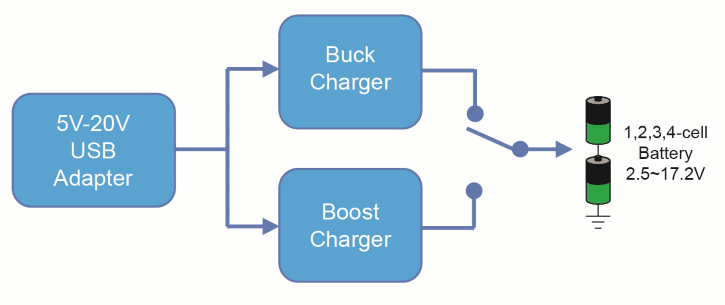
Figure 2 shows an approach based on a buck charger or boost charger concept. It takes the USB adapter voltage and uses a buck charger or a boost charger, depending on the input/output voltage relationship. While this approach eliminates the additional power loss in the pre-boost approach, it still requires an additional boost charger, which adds solution cost and size.

Fig. 2: The buck charger or boost charger approach
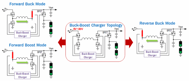
Enter the buck-boost topology approach. A buck-boost topology can operate in buck mode when there is input to output, in boost mode when there is output to input or in buck-boost mode when there is two-way input ≈ output. Such flexibility allows for a better design with the smallest solution size and best overall efficiency. It achieves all of the system designer’s requirements. The first USB-C buck-boost battery charging solution on the market is the Intersil ISL9237 buck-boost charger. Figure 3 shows the topology of the ISL9237. The device consists of four switching FETs and an inductor, as well as a battery connecting FET (BFET). The four switching FETs are grouped into a forward-buck leg and a forward-boost leg. By operating either leg, this topology can operate in forward buck mode or forward boost mode for charging the battery. It can also operate in reverse buck mode to deliver power out of the USB port for charging an external electronic device, such as a tablet, smartphone or the emerging portable power bank products that can charge any device.

Fig. 3: A buck-boost charger topology approach
The ISL9237 offers a rich feature set and is an SMBus charger capable of communicating with an SMBus host. It is compliant with USB 3.1, which doubles the speed of USB 3.0 to 10Gbps, and the latest Intel IMVP8 PROCHOT# and PSYS requirements for protection against battery voltage drop, adapter over-current, battery over-current and overheating. It provides two-level adapter current limit with fully programmable magnitudes and durations to take advantage of the adapter’s surge current capability. It also supports any travel adapter, including those that do not disclose their current handling capability.
With the arrival of the ISL9237 USB-C buck-boost battery charger, mobile PC systems and other portable devices will now be able to employ optimal two-way power delivery using the reversible USB Type-C connector. This is a major evolutionary step for consumers, who will no longer have to fumble around for the right orientation to insert the cable. The new USB-C power delivery approach using a USB Type-C connector simplifies the way computers and external electronic devices receive and deliver bi-directional power and data. The USB-C ecosystem is ushering in a future where just one tiny cable is needed for any device.
Advertisement
Learn more about Intersil


