Selecting a logic analyzer for today's demands
Playing an increasing role in integrating hardware
and software, logic analyzers require many new features as well as manufacturer support
BY PHIL STEARNS
Hewlett-Packard
Colorado Springs, CO
The growth of microprocessor technologies has created a greater role
for the logic analyzer and has made choosing one more complicated. Each
new generation of microprocessors seems faster, wider, and more complex.
At the same time, the logic analyzer has evolved from its traditional role
as a hardware debug tool to become a key tool for the integration of hardware
and software. A new logic analyzer must have the features necessary to
function in its new role and the power to keep up with microprocessor technology.

The tangible part of the designer's decision in selecting an analyzer
can be reduced to three facets: probing, acquisition, and analysis. Equally
important are intangible issues such as integration with other tools, the
technology road map of the logic analyzer platform, and the manufacturer's
support of its products.
The tangibles
Probing
Data acquisition and analysis tools are only as effective as their interface
with the target system. The engineering maxim “garbage in, garbage
out” definitely applies to probing. However, this link in the measurement
chain is usually assumed (occasionally incorrectly) to be acceptable. The
designer should measure the task of probing against the following criteria
before purchasing a logic analyzer.
The test system should be immune to noise. EMI and ESD noise
lurk everywhere within the test environment, and they can cause false triggers
and data corruption. Analyzer probes that are susceptible to these effects
will add one more variable to the debugging equation. Is a glitch coming
from the device under test or from the probe? Look for a probing solution
with a high immunity to transient noise.
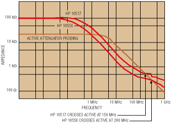
High impedance minimizes the effect of probing on the circuit. High input impedance will ensure that the effect of probing on the circuit
is minimal. Although most probes are acceptable for lower frequencies,
probing effects become more pronounced at higher frequencies. Refer to
a Bode plot of the vendor's probes to determine its impedance at the frequency
at which testing is being performed (see Fig. 1 ).

Fig. 1. Manufacturers' Bode plots help users to determine a probe's
impedance at the frequency at which they will be testing.
The probe should be rugged. A flimsy probe can cause unintended
open circuits, adding yet another variable to the debugging equation. A
probe that is mechanically designed to relieve strain ensures a rugged,
reliable connection.
Probing tools should take connectivity into account. Flying leads
are a flexible probing solution, but they can be aggravating and error-prone
when connecting them in large quantities. Look for probing solutions that
are designed for a specific chip package or bus. As an alternative, consider
reliable termination adapters. Termination adapters, made by vendors such
as 3M and Mictor, give easy and reliable debugging connections when a package-specific
probe is not available. The tradeoffs are board space, and the design time
needed to route signals to the connectors.
Acquisition
Many engineers focus on the acquisition section of the measurement chain
when they purchase a logic analyzer. Acquisition parameters can be easily
quantified in terms such as state and timing acquisition speed, channel
count, and memory depth. Engineers see these parameters as a way to objectively
meet their most basic analysis needs.
The driving question when determining data acquisition needs is “How
much?” If the designer works on the bleeding edge of digital design,
the more data the better. Other designers find it best to purchase for
current and immediately anticipated needs.
It is too difficult to predict the future of digital devices or the
devices that test them to plan for a future design start. A reliable vendor
will provide an upgrade path or offer trade-ins to protect a logic analysis
investment. However, if the designer cannot count on the logic analysis
vendor to protect the investment, the designer should buy as much acquisition
headroom as can be afforded.
State speed. State speed refers to acquisition that is controlled
by the clock of the device under test. Information is acquired during the
data-valid window of each clock cycle. There are two guidelines for determining
the state speed that are needed.
First, the state speed should be faster than the system's data rate,
not its clock speed. If a designer is working on a 133-MHz processor that
has a 66-MHz data bus, then it is likely that the needs will be satisfied
with a state acquisition speed of 70 MHz or faster. Unless the engineer
works with a RISC processor or with multiple processors and domains, the
clock speed will be faster than the system's data transfer.
Second, state data acquisition is only as good as its weakest specification.
A logic analyzer that does not have a setup-and-hold time commensurate
with the state speed may give erroneous data.
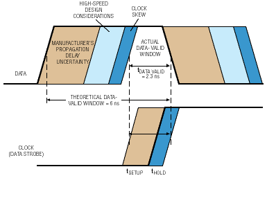
Consider the case of a Philips Semiconductor 74ALVT16374 high-performance
bus latch running at 166 MHz (see Fig. 2 ). Theoretically, the data-valid
window is 6 ns (1 divided by 166 MHz). However, when the manufacturer's
propagation delay uncertainty, high-speed design considerations, and clock
skew are all subtracted, the actual data valid window is 2.3 ns.

Fig. 2. A 74ALVT16374 bus latch running at 166 MHz demonstrates–with
an actual data-valid window of 2.3 ns–how a logic analyzer that does not have a
setup-and-hold time commensurate with the state speed may give erroneous data.
If the logic analyzer's setup-and-hold time is longer than 2.3 ns,
then data may be acquired when it is not valid. The designer should use
the vendor's worst-case estimates of these specifications to determine
the state speed needed.
Timing speed. A logic analyzer's timing mode lets the user asynchronously
capture the nature of a digital signal that underlies its state (synchronous)
behavior. Five samples per clock cycle give the designer good insight into
how the state information latches.
Acquisition depth. Deep memory lets a designer find problems
that occur far before or after the symptom that they cause. Deep memory
is also useful for the software or firmware engineer who is disassembling
long traces of code. As long as the logic analyzer has the analysis tools
to let the user make sense of large quantities of data such as filters,
store qualification, and inverse assembly, more is definitely better.
Channel counts. Plan channel counts to meet the needs of the
entire system, not just the microprocessor. Channel counts evolve more
slowly than processor speeds, so headroom is less of an issue.
Analysis
The analysis features of a logic analyzer transform it from a simple
measurement device to the digital designer's most important tool. A logic
analyzer should have the measurement tools and analysis toolsets to provide
insight into every area of a system's operation.
Measurement tools. A logic analyzer becomes even more versatile
when combined with different measurement tools. An integrated oscilloscope
adds visibility into parametric signals. Most logic analyzers purchased
today have this feature.
Pattern generators are another popular measurement tool. Integrated
stimulus and response permits characterizing designs and simplifies conformance
testing. These modules are even more useful when they can be time correlated
across the measurement domains.
Analysis toolsets. Analysis toolsets harness the power of a logic
analyzer. Advanced filtering and triggering make it easy to find obscure
bugs. A software analyzer tool permits correlating real-time traces with
the associated source code. A system performance analyzer enables progression
from debugging a system to optimizing it. A compare tool tests a device
against its ideal.
The intangibles
Ease of use
First, the user interface should feel like a natural extension of the
target system–not the logic analyzer. Second, an analyzer's interface
should be intuitive enough to make it easy to take the first measurement,
without making it cumbersome to take the one hundredth. Finally, flexibility
and simplicity should not be mutually exclusive.
Complete solutions
The logic analyzer is a critical part of the digital debugging environment,
but it is not the only part. For hardware/software integration, the extended
measurement chain may include a preprocessor, a run control probe, and
a debugger in addition to the logic analyzer's probing acquisition and
analysis.
These components will be more tightly integrated and reliable if purchased
from a single manufacturer, or from cooperating vendors that have integrated
their components. If a complete solution does not exist for the target
system, the designer may need to piece together components from different
vendors or create a custom solution.
Manufacturer support
Logic analysis systems are a large investment. A manufacturer can protect
and enhance the designer's investment by providing a path for technology
migration, and with engineering support.
The overall cost of a logic analyzer will be much lower if the manufacturer
has a history of supporting its platforms. A platform that is frequently
upgraded will have a long, useful life. If the platform cannot be effectively
upgraded, the manufacturer should at least offer a trade-in to its new
platform.
Advertisement


