Selecting display backlighting for portable, handheld devices
Which technology to use? Today’s OEMs have multiple options
BY DAVID DeAGAZIO
Global Lighting Technologies
Brecksville, OH
http://www.glthome.com
OEMs who need to backlight displays in portable/handheld devices from mobile phones to medical diagnostic devices are looking for a high level of performance, efficiency, and economy. What backlighting technology is used depends, of course, on the device, the display, and the manufacturer’s individual requirements for it.

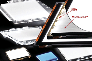
Technologies like MicroLens pixel-based edge lighting offer improved backlighting LCDs and keypads.
Monochrome display lighting
Electroluminescent (EL) backlighting is still used where a relatively simple passive-matrix monochrome display is required with geometrical flexibility and brightness of around 30 ft-L. This includes desk clocks, watches, night lights, pagers, and some cell-phone keypads. EL lamps are constructed using screen-printable polymer-thick-film compositions.
Advantages of EL backlights include uniform illumination of complex shapes, thinness, flexibility, and light weight. However, their brightness degrades over time, they need high-voltage inverters, and they are electronically noisy.
Another technology for monochrome displays is fiber-optic (FO) backlighting. Using LEDs as the light source, this technology, provides the brightness of EL or better, but with longer life, no degradation in brightness, lower power requirements, and no heat or EMI.
Fiber-optic backlights can be supplied as thin as 0.013 in. and can be customized for use with unusual geometries, such as circles, semicircles, ovals, and holes. Disadvantages include cost and overall efficiency, and it can be difficult to find a route for the fiber-optic “tail” in smaller devices, where space is at a premium.
Active-matrix color displays
As portable devices become increasingly sophisticated, higher-performance lighting technologies are needed. They have to backlight the color TFT LCDs used to provide full-motion video, dimming, and touchscreen capabilities in mobile devices.
Cold-cathode fluorescent lamps (CCFLs) can provide high brightness, but their size, fragility, and the relatively large inverters needed to power them limit their use to 7-in.-and-larger displays. That takes them out of the running for just about all today’s hand-held applications.
Backlighting issues were going to be settled once and for all by organic light-emitting diode (OLED) displays, touted as the next-generation display technology when they were introduced several years ago. Requiring no backlight and available in monochrome and full-color versions, OLED modules were to offer an efficient, economical emissive passive-matrix displays capable of a wide variety of animations, patterns, and backgrounds. Some of the advantages OLED displays claim are better contrast ratio than LCDs, wide viewing angle (to 160°), fast response time, and thinness.
As it turned out, OLED displays are more expensive than backlit LCDs. They are currently used in only a small portion of today’s handset applications, as material, fabrication, and shelf life issues have delayed wide adoption in the consumer market. (One indication that OLED technology still faces serious roadblocks is the fact that a major OLED-display manufacturer pulled out of the market in 2007 because worldwide demand lagged far behind expectations.)
Thus LCDs still hold their dominant position as color displays for portable and handheld devices, and LEDs have increasingly become the most effective solution for backlighting them. As a result, the choice of what type of backlighting to use for TFT LCDs often comes down to which LED-based backlighting technology is the best for the application.
LED backlighting
For today’s mobile phoneswith their high information content, Internet access, digital cameras, and full-motion video capabilityfull-color displays require white LED backlighting that must be more efficient than ever. That includes enhanced brightness, crisper color, and lower power consumption for longer battery life. And phone manufacturers want a smaller form factor, with fewer components, at the most economical cost.
The ideal LED-based backlighting technology would, while meeting the brightness requirements of the application, reduce one or more of the following parameters: cost, power, thickness, number of LEDs needed, and/or number of optical films.
Many portable/handheld-device designers have used direct LED backlighting. The LED light source eliminates noise and the need for an inverterletting the device run directly from batteriesand provides more design flexibility. It employs top-firing surface-mounted, nonfocused (120º viewing angle) LEDs. The brightness is good, but since there is little or no way for this technique to channel the light uniformly, a lot of LEDs are needed to achieve good uniformity. Due to the number of LEDs and thickness required, cost and board real estate are issues.
Another LED-based technology, the light array, offers very high brightness and fits small LCD backlights. It consists of a matrix of LED chips, typically mounted inside a white plastic frame on an LCD’s pc board. The white frame helps focus the light somewhat, but, for an LCD with, say, a 16 x 61-mm viewing area, as many as 36 LED chips may be needed.
Thus, white-LED arrays are more expensive than other technologies, and the arrays are typically only viable in less-expensive colors, such as yellow-green, not suitable for full-color high-resolution displays. As might be expected, the arrays also tend to run hot.
Edge lighting
A common display lighting option today is to use LEDs and light-guides in an edge-lighting approach. There are a variety of methodologies to extract light from a light guide: printed dot, etched dot, V-groove, and pixel-based (see table ).
Edge-lighting approaches
| Technology | Efficiency | 2-D pattern possible?* |
| Printed dots | Low | Yes |
| Etched dots (chemical, laser, etc.) | Good | Yes |
| V-groove | Very good | No |
| Pixel-based | Very good | Yes |
| *indicates uniform, visual appearance | ||
In these technologies, side-firing LEDs are used that focus their light into a high-performance light guide. Since the LEDs are located on the edge of the guide, this approach offers many benefits, including a more uniform, cost-effective, thinner solution that can minimize the number of LEDs needed.
Because of the quantum leap in LED brightness, edge-lit light guides are generally the lighting technology of choice for designers. However, it is critical that the light extraction be highly efficient and uniform.
Many experts have found pixel-based light-extraction offers the best mix of high efficiency and control of lighting uniformity. The MicroLens pixel-based light extraction technology, for example, uses LEDs so efficiently that fully integrated backlighting modules can have higher brightness, crisp color, and uniformity of 80% to 90% on average, while being extremely thin, using less power, and reducing complexity, size, and cost.
In the MicroLens design, micro-optical elements are molded directly into a light guide. As many as 28,000 lenses/cm2 are used on the top and bottom surface of the light guide. The approach provides single-LED monochrome, bicolor, or tricolor backlights in sizes from 0.24 to 15.4 in. diagonal with brightness to 15,000 nits. Capable of being placed in packages only 0.60 mm thick or less, the devices can be used both for full-color high-resolution display and keypad lighting.
A unique “transition” area that extracts light precisely at each point across the panel is an important attribute of MicroLens backlights. The light produced is more specular (collimated) and incident light rays are controlled, redirecting their emission angles from the light guide while minimizing scatter.
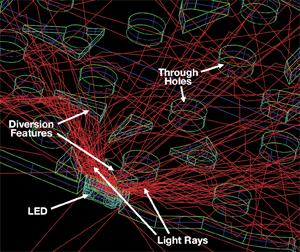
The approach also works for keypad illumination, where the main challenge with molded light guides has been that the light would generally terminate at the edge of the first through-hole, making it extremely difficult to achieve uniformity. However, use of advanced optical simulation (see Fig. 1 ) lets designers mold diversion features, which “bend” a portion of the light around the through-hole. Diversion features let manufacturers achieve excellent uniformity with far fewer LEDs and fewer, if any, hot spots and dark areas.

Fig. 1. Optical simulation of a molded light guide shows how the diversion features direct light rays around through-holes.
Manufacturing efficiencies
Chemical, laser-etched, MicroLens, and V-groove techniques all offer manufacturing efficiencies. However, MicroLens technology also provides full control of the light guides’ size, shape, depth, density, randomization, and orientation.
Light guides such as MicroLens that can be made in a thin package and have mechanical holding features either designed into the backlight or onto a custom-designed backlight frame allow chip-on-glass or chip-on-flex LCDs or the entire display assembly to be easily mounted into the host application.
In many cases, LEDs are attached to a flex-circuit to provide a “plug-n-play” solution, and the LEDs are located in the corner(s) of the backlight. With this approach, a designer needs fewer white LEDs, thus cutting power, assembly time, cost, and size. ■
For more on display backlighting, visit http://electronicproducts-com-develop.go-vip.net/opto.asp.
Advertisement
Learn more about Global Lighting Technologies


