Selecting the right dc/dc converter for portable apps
The proper converter topology depends upon the application and what parameters are most critical
BY KEVIN TRETTER
Microchip Technology
Chandler, AZ
http://www.microchip.com
The ubiquity of portable electronics has forced system designers to focus more and more on the design of power-management circuitry. Today’s engineer must find ways to extend battery life while still maintaining performance.
On top of this, many portable applications are becoming even more compact, forcing circuit designs to fit into smaller and smaller form factors. The design of the power-management circuitry in such systems is critical, and an understanding of the various dc/dc converter architectures is needed to optimize the overall performance of the design.
As the name implies, a dc/dc converter converts a direct current at one voltage potential to a direct current at a different voltage potential. This is a critical function in battery-powered applications, where the voltage across the battery or batteries can change as the cell is depleted.
For example, a single AA alkaline battery produces a nominal voltage of 1.5 V when fully charged. As the battery cell becomes depleted, this voltage can drop to as low as 0.9 V.
A dc/dc converter may be required to boost the battery voltage to a different voltage potential, in order to operate various ICs in the system. There are a variety of different dc/dc converter topologies available, including linear regulators, switching regulators and charge pumps.
Linear regulators
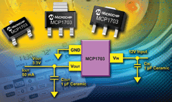
A linear regulator uses a voltage-controlled current source to create a given output voltage. There are several different types of linear regulators, but for battery-powered applications, the most common is an LDO, such as the MCP1703. This type of linear regulator uses a p-channel pass transistor as a variable resistor with feedback, in order to regulate the output voltage.

Fig. 1. The MCP1703 LDO is one type of dc/dc linear regulator.
As this architecture relies on adjusting a resistive element to create a given output voltage, an LDO (or any linear regulator) can only create an output voltage that is lower than the input voltage. The minimum required differential voltage between the input and the output is called the dropout voltage. Since an LDO uses only a single p-channel transistor, it has a lower dropout voltage than the other linear-regulator topologies.
Another disadvantage of LDOs is that they can be inefficient. The resistive element that is needed to drop the input voltage to the required level dissipates power in the form of heat. This is considered lost energy, as it is being supplied by the input source but is not being delivered to the output.
This can also cause thermal issues, as the regulator dissipates more and more energy in the form of heat. A system designer must be aware of the input and output voltage and current requirements. LDOs may not be a viable option for systems that require a large voltage drop and/or a large output current, due to the issues caused by self-heating.
Despite these limitations, LDOs do provide some inherent advantages over other types of dc/dc converters. One advantage is that LDOs are relatively quiet in terms of noise, as there are no switching elements associated with their use. This can be very important to noise-critical applications that involve sensitive measurements, or to systems that must pass strict governmental regulations.
Additional advantages include ease of use and overall size. The most basic LDOs come in three-pin packages, providing an input, an output and a ground reference. Most LDOs require only a capacitor at the output for stability, providing for a very small system size. Finally, LDOs are typically more cost-effective than the other dc/dc regulator architectures.
Switching regulators
In their most basic form, dc/dc switching regulators use a diode, inductor and a switch in order to transfer energy from the input to provide a given output. Switching regulators can be configured in several different topologies, including buck, boost and buck/boost.
A buck switching regulator provides a regulated output voltage that is lower than the input voltage, similar to the functionality of a LDO. A boost switching regulator provides an output voltage that is higher than the input. This is a function that cannot be accomplished with a LDO. Finally, a buck/boost topology provides a regulated output across a range of input voltages that are above and/or below the output.
The inductor inside the switching regulator acts as an energy-storage device, and is much more efficient than the resistive element used in linear regulators. A switching regulator can achieve efficiencies of 85% or higher. Except in very specific conditions, an LDO cannot achieve this level of efficiency.
Due to their high levels of efficiency, switching regulators are a better fit for higher-power applications, such as regulating a 24 V power bus down to 5 V and supplying 500 mA to the load. In this example, a LDO would dissipate over 9 W of energy in the form of heat, while only delivering 2.5 W to the load! For many portable applications, implementing a large heat sink or a cooling fan to account for thermal issues is not an option.
As the name implies, switching regulators have a switching element, typically a transistor that is turned on and off rapidly. The frequency of this switching varies based upon the regulator’s design, and generates harmonics around the switching frequency. This switching noise can be problematic for circuitry that involves sensitive measurements, or for products that must past strict governmental regulations regarding electromagnetic interference.
IC manufacturers are making switching regulators easier and easier to use. However, most switching regulators still require the inductor to be external to the IC. The larger the inductor, the less effect the inductor current ripple will have on the regulated output.
Hence, it is not practical to integrate the inductor in silicon. Depending upon the size of the inductor, this can be a considerable increase in the overall solution size. This external inductor can also create noise issues, so care must be taken when laying out the printed circuit board.
Charge pumps
A charge pump is a type of dc/dc converter that uses a capacitor as an energy storage device. Switches connect the plates of the capacitor to the input voltage in such a way that they can double, triple, invert, halve or even create an arbitrary regulated output voltage, depending upon the circuit topology. Because charge pumps charge and discharge capacitors to transfer energy, the amount of output current that this type of converter can provide is relatively low, compared to the other converters mentioned-typically no more then a couple hundred mA.
In terms of efficiency, noise, and solution size, charge pumps fall somewhere in between linear regulators and switching regulators. The efficiency of charge pumps is better than LDOs, although switching regulators can achieve even higher efficiencies. The switches inside of a charge pump create the same type of switching noise as a switching regulator, but do not require an external inductor (which radiates that switching noise). Charge pumps also require an external capacitor in order to minimize the voltage ripple applied to the load. This external capacitor needs to be much larger than the internally switched capacitor, and can take up valuable circuit-board space.
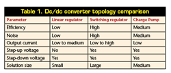
All three of the dc/dc converters discussed above have advantages and disadvantages associated with them, as Table 1 shows.
Table 1. Dc/dc converter topology comparison

If extending battery life is a priority, then a highly efficient switching regulator may be the best solution. If noise is a big concern, then a linear regulator is an attractive solution. Regardless of the application, focusing on the power-management circuitry is critical in achieving the desired system performance. ■
For more on dc/dc converters, visit http://www2.electronicproducts.com/Power.aspx.
Advertisement
Learn more about Microchip Technology


