Sensors have transformed our world. While it is easy to add limit switches to detect hard stops, alert levels, or alarm conditions, the ability to obtain more resolute information as to the exact state of a system has allowed designs to become predictive instead of purely reactive.
Some sensors are easy to deal with. A temperature sensor, for example, can easily couple to a manifold. A pressure sensor can easily couple to a tank. In most cases, a current sensor can easily couple to a conducting path.
But, sensors do not always go easily where they are supposed to. For example, shaft encoders must mechanically couple to the rotating machine. This may result in a more complex assembly using gears, shafts, and rollers. This can introduce errors and sloppiness to the measurement since angular movement needs to overcome mechanical tolerances, especially when directions change.
One family of sensors that is particularly hard to couple to are strain gauges. Here the deformation of a transducer typically causes a change in resistance or generates a voltage. Strain gauges and load cells are typically planar sensors. It can be very difficult to position them in tight spaces and multi-axis applications. When angular components of strain are present, trigonometric processing may be needed to compensate for accuracy. This translates into more processing power than would otherwise be needed.
What’s more, many strain gauges are not electrically isolated from the central CPUs. They can be with additional circuitry and power coupling, but this adds space and cost. Isolation is important because—especially with mechanical machines—failures can introduce electrical hazards.
A New Phase
A clever approach to this dilemma comes from Avago, who has an innovative solution based around the elasticity of Polymer Optical Fiber (POF). When a reference fiber runs in parallel with a fiber that is coupled to an axis of stress, a split modulated signal injected into both fibers will result in a measurable phase shift that is proportional to the strain introduced (Figure 1).
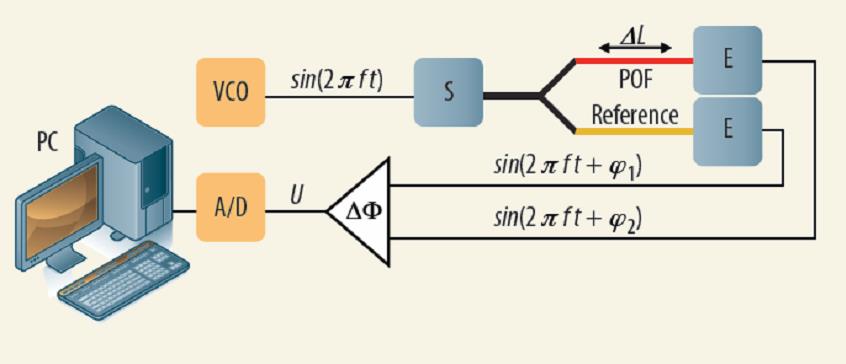
Figure 1: Systems designers will appreciate how easy it is to generate a reference signal and simply measure the differential phase difference. This can be processed or applied to a Look-Up Table for fast control loops. (Source: Avago)
Avago calls this technique Optical Phase Interrogation (OPI) and has opened up new possibilities for the use of Glass on Fiber (GOF) as well as POF (with core diameters QFBR-SO1N001Z; a self-contained OPI unit that compares the fixed-frequency pulsed-sinusoidal signal through two fibers and generates a reference phase shift using visible (650 nm) LED technology. It features an Ethernet connection as well as digital I/O and a 4-20 ma industrial interface for easy integration and test into a variety of design needs.
Help is also available in the form of the OPI development kit (QFBR-S01EK001Z) from Avago. This kit uses an I2C serial bus to also patch in a variety of other sensors, storage resources, and test interfaces. It also has an ARM Cortex M3 processor with averaging, compensation, and control algorithms, as well as self-test, and a boot-loader.
Designers can always design their own interfaces based on this technology. In order to do this, or to optimize performance, designers will need to determine the modulation frequencies for the desired resolution, sensitivity, and optic-fiber length. Designers will also have to bias signals to maximize the dynamic range that may include attenuations, offset compensations, and gain calibrations. Also note that this technique is uni-polar and will only measure stress from a zero-point reference. It will not measure compression.
If you wish to learn more, a Tech Note and White Paper from Avago can delve deeper into this technology.
Advertisement
Learn more about Avago Technologies


