By Richard Quinnell, Editor, Special Projects, Technical
Also known as inertial sensors, accelerometers are critical elements in key applications such as automotive air-bag deployment, smartphone motion tracking, and industrial predictive maintenance. These varying needs have resulted in an even more varied array of accelerator products from which designers can choose. Fortunately, by focusing on a handful of key decisions, developers can quickly zero in on the right kinds of devices for their application.
Despite the multitude of options available, accelerometers are all based on the same basic principle: inertia. A proof mass within the accelerometer’s structure can readily move in at least one dimension. Because of inertia, that proof mass will tend to stay in place when the surrounding structure undergoes acceleration (i.e., changes its motion) along that same direction. Sensing systems within the accelerator detect the proof mass’s movement relative to the surrounding structure, and interface circuits deliver a corresponding signal to the outside. A spring of some kind provides a restoring force to return the proof mass to its initial position once the acceleration has ended.
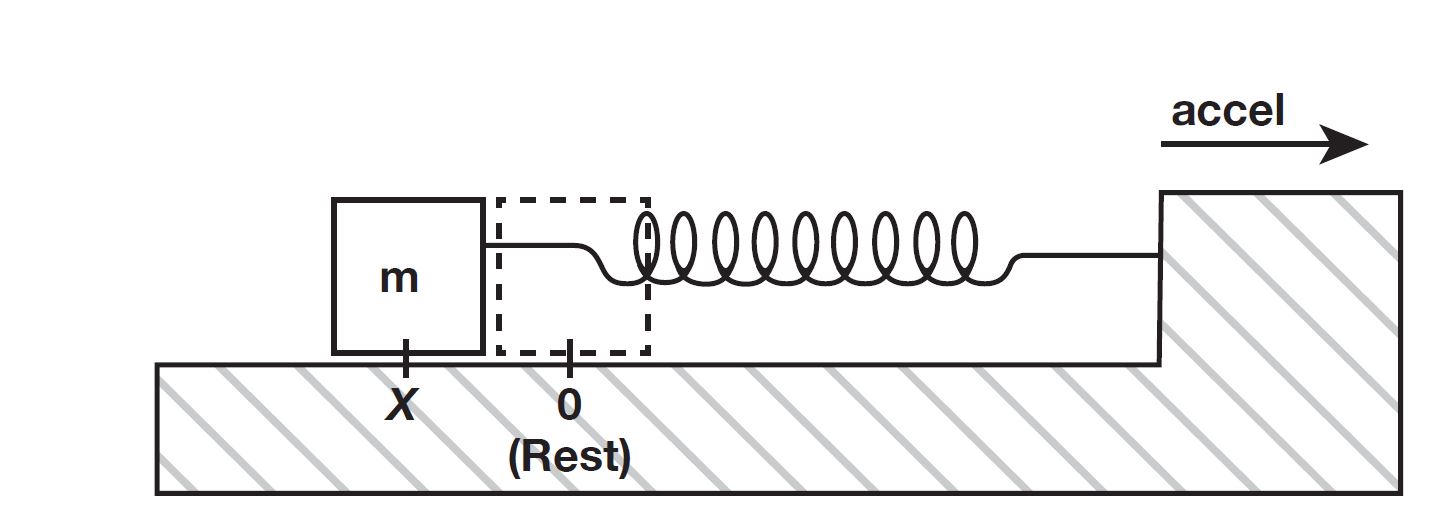
Fig. 1: Accelerometers leverage the inertia of an internal proof mass to sense changes in motion.
The many variations among commercial accelerometers are the result of differing mechanical and material designs for the proof mass and surrounding structure, the choice of sensing technique, and the type of signal that the interface provides. Options such as the use of microelectromechanical system (MEMS) structures or the choice of capacitive versus piezoelectric sensing offer various pros and cons.
In practice, however, these choices are not, in themselves, particularly relevant to designers. What is important to designers is the performance result that the vendor achieves from its choices among these options. Key performance specifications for designers include measurement range, sensitivity, precision, and accuracy, along with a variety of operating characteristics.
When choosing an accelerometer, then, designers need to first think through their application’s needs. How much acceleration will their device normally experience? What extremes might it see? What is the operating environment like? Are there dimensional or mounting constraints? What kind of interface is needed, analog or digital?
Answering these kinds of questions first will make it easier to narrow down candidates. Developers should always bear in mind, too, that everything on or near the planet is continually undergoing an acceleration of 1 g (9.8 m/s2 ) toward Earth’s center, creating measurement offset in that direction.
With application needs in mind, a place to begin sifting through the many options is with the functional parameters: number of axes, range, and mounting. The first functional decision that developers need to make is how many axes, or orthogonal directions, the accelerometer must sense. Devices are available for one- (X or Z), two- (X-Y), and three-axis (X-Y-Z) sensing, with the X-Y plane generally referring to the device’s mounting surface. There are also accelerometers such as the TDK/InvenSense ICM-20600 that are described as six- or nine-axis devices, but these are not just accelerometers. A six-axis device typically includes gyroscopic sensing of rotation in the three linear axes, and a nine-axis device also includes magnetic field sensing in the three linear axes.
In general, a price-constrained application will use only as many sensing axes as the application requires to save cost in both the sensor and the electronics that convert the sensor signal into a useful measurement. A safety monitor on an elevator, for instance, needs to sense only in the vertical direction. A tilt monitor, on the other hand, needs two dimensions — X and Y — to determine the angle between the sensing plane’s vertical (Z) and the pull of gravity.
Applications requiring full three-axis sensing, such as determining a system’s orientation in space, can be served using a single X-Y-Z accelerometer or a combination of one- and two-axis sensors as cost and placement needs dictate.
Three-axis sensors used in smartphones and automobiles are an exception to the cost generalization, though. Volume production has driven cost down for such sensors, making them possibly the least expensive option for certain applications. Typically, however, they operate in the low sensing range.

Fig. 2: Their inclusion in consumer devices such as smartphones and automobiles has dropped the size and price of three-axis accelerometer chips such as this IAM-20381 from TDK/InvenSense. (Image: TDK/InvenSense)
Sensing range is the second key functional decision that designers need to make. Broadly described as low, medium, or high, the sensing range for accelerometers is specified in multiples of g — the acceleration of gravity — and generally is symmetric around zero and the same for all axes.
Accelerometers used in smartphones fall in the low range for accelerometers, typically ±3 g or so, as they are concerned primarily with human movement. Sensors for monitoring machinery may be more demanding and need the wider medium range of about ±30 g.
For the most aggressive types of movement, devices with a high range are also available like the STMicroelectronics H3LIS331DL , capable of sensing ±400 g. Often, devices are available in families encompassing varying ranges. For instance, the Analog Devices ADXL344 family offers ±2-g, 4-g, 8-g, and 16-g options. A rough rule of thumb is to choose a range more than twice the maximum acceleration expected to allow for unexpected conditions.
Sensing range should not be confused with the accelerometer’s shock range. Operating outside of the sensing range results only in distortion or clipping of the output signal. The shock range is the maximum acceleration that the device can experience without being damaged.
The accelerometer’s packaging and mounting style are a third key functional choice for designers to make. Many accelerometers are available in chip form for mounting on a circuit board. Single-axis accelerometers can have the sensing direction either in the chip’s mounting plane or normal to it. Two-axis devices typically sense in the mounting plane only.
Another mounting style available is the encased accelerometer that mechanically attaches to a non-electronic supporting surface such as machinery housing. Such devices can be attached using bolts, screws, adhesives, magnets, or clamps or simply be hand-held.
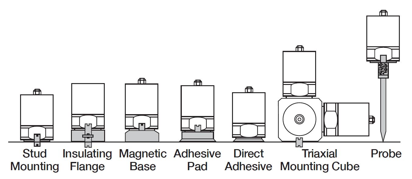
Fig. 3: Encased accelerometers are available with a variety of mounting options, but the choice can affect the achieved sensing bandwidth. (Image: IDS Innomic)
The mounting style chosen has an important effect on an accelerometer’s frequency response. As with any kind of sensor, accelerometers have limits on how rapidly they can respond, and as with any mechanical system, they can resonate with vibration at the right frequency. The key performance parameters to consider, then, are the sensor’s bandwidth and resonant frequency.
Bandwidth is the frequency range over which the sensor’s measurements will be consistent (i.e., a “flat” response) and is usually specified as a tolerance band in terms of percentage deviation from the accelerometer’s performance at a reference frequency — often 100 Hz. To get a full picture of a device’s behavior, however, designers should look for a frequency response curve in the data sheets.
For many applications, it is essential that the accelerometer’s frequency response extends all the way to DC. This is essential for applications that are measuring orientation using gravity to determine which way is “down.” It is also important for those applications that are integrating acceleration to determine velocity or movement.
There are numerous other performance parameters for designers to explore as well. These include:
- Sensitivity. This is a measure of how strong a signal the accelerometer generates for a given acceleration, often measured in mV/g for analog devices or as the number of bits representing 1 g in a digital device. Sensitivity and range often go hand in hand, with a greater range typically implying reduced sensitivity. This parameter is not to be confused with transverse, or cross-axis, sensitivity. Cross-axis sensitivity refers to the amount of signal that appears in the sensor for one dimension (say, X) when the acceleration is strictly orthogonal to that dimension — Y or Z. Such signals are error sources and should be as small as possible.
- Noise. This parameter can be expressed in several different ways, including RMS or as a spectral value. Designers should consider noise specifications in conjunction with sensitivity.
- Linearity. This parameter indicates measurement consistency over the accelerometer’s sensing range. Ideally, a unit change in acceleration should produce a unit change in the output signal regardless of how strong the absolute acceleration may be. In practice, calibration may be required to correct some non-linear operation.
- Temperature sensitivity. Because they are mechanical systems, accelerometers are susceptible to temperature, which causes dimensional changes as it varies. Temperature sensitivity measures how significant an impact a temperature change will have on the output signal.
There is also a host of practical considerations that affect an accelerometer choice in the final design. These include the device’s supply voltage, current draw, package size, degree of robustness — commercial-, industrial-, or ruggedized-grade — and the like. Sensors may generate an analog output signal or include an integrated ADC to provide a digital signal. The digital signal interface may conform to an industry standard such as I2 C or SPI or, in rare cases, produce a pulse-width modulated (PWM) output. The accelerometer may be a raw sensor or an integrated device with signal conditioning and controls built in.
With all of these parameters and variations to consider, it should come as no surprise that there are many vendors offering accelerometers, often focusing on a few types and application spaces. The table below provides a partial list of representative vendors that developers can use to jumpstart their search for the best match to their needs.
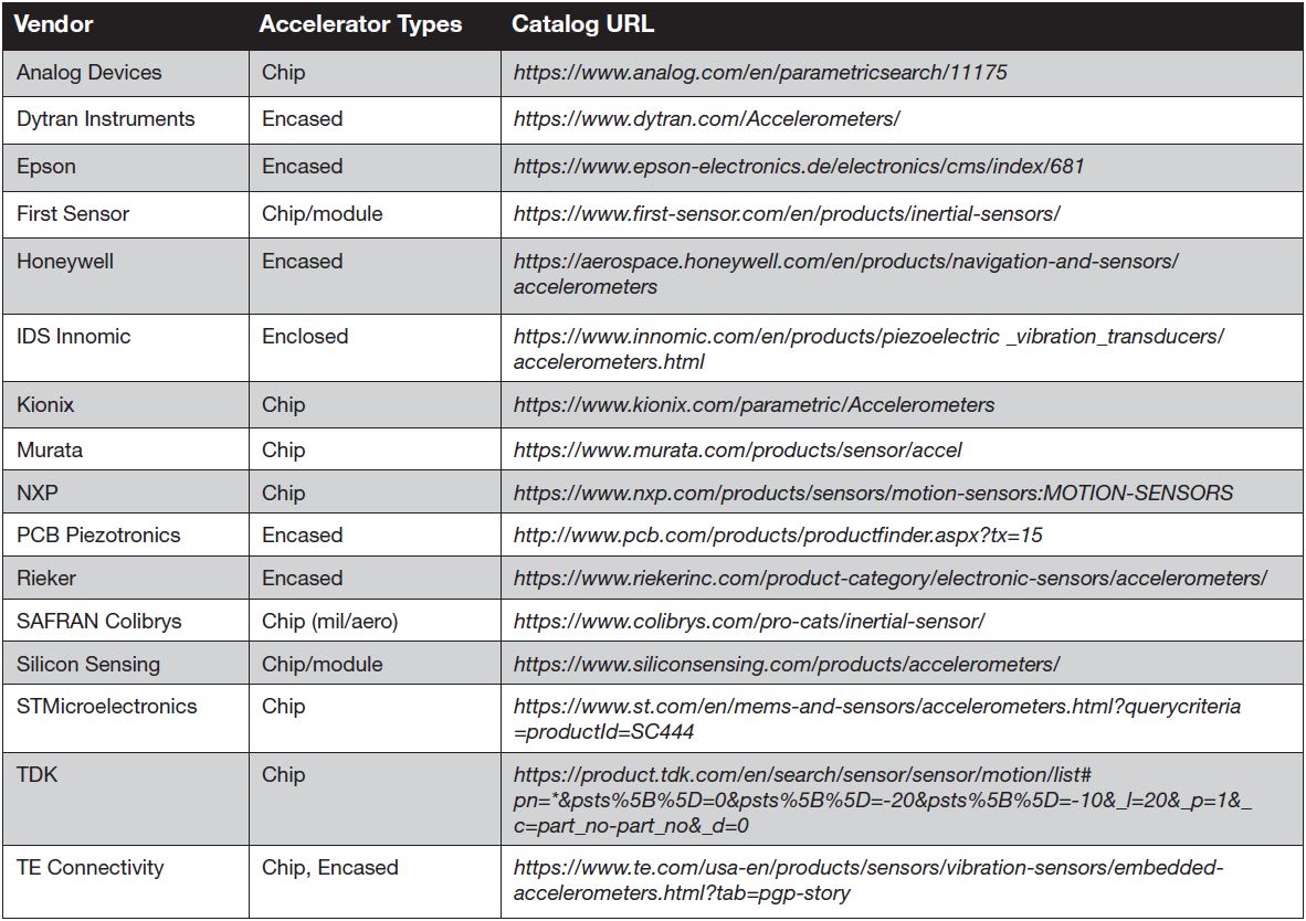
Many of the above vendors offer directly comparable products for common applications, while others specialize in niche devices for which there are few competitors. Regardless, the right choice of accelerometer is so highly application-dependent that developers should consider enlisting help in making a final selection once the essential needs are well-defined and the choices narrowed down. The vendor’s support can prove an essential final factor in choosing the right accelerometer for a design.
Advertisement
Learn more about Electronic Products Magazine


