By Tim Resker, global business development manager, Coto Technology, Inc.
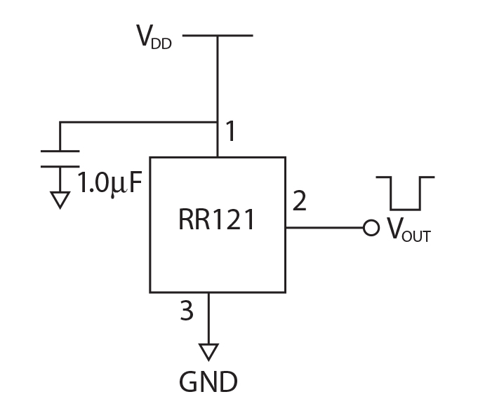
The tunneling magnetoresistance (TMR) sensor itself is a three-pin device — power, ground, and digital output (push-pull or open drain). The power supply, Vdd, can range from 1.7 V to 5.5 V. The output goes LOW when the magnetic field at the sensor reaches the operate field threshold of the sensor, which can be as low as 9 Gauss or 0.9 milliTesla. The output goes HIGH when the field is reduced to below the release field threshold of the sensor (about 5 Gauss for a 9-Gauss operate sensor).

Fig. 1: The TMR sensor is a three-pin device.
It’s also worth noting that a 9-Gauss operate threshold of a TMR magnetic sensor allows for pairing with very small, low-cost magnets — in some cases, even commonly available plastic-bonded ferrite magnets.
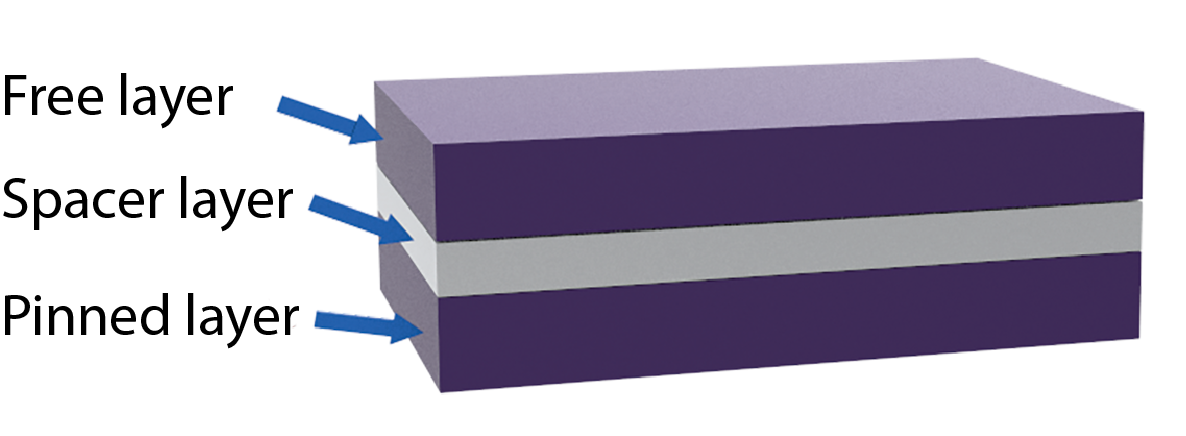
A TMR sensor is comprised of a magnetic tunneling junction (MTJ) element and CMOS circuitry. An MTJ element is a multilayer, thin-film stack composed of a sandwiched structure with a free layer, a spacer layer, and a pinned layer (Fig. 2 ). The spacer layer (made of dielectric oxide material) separates the ferromagnetic free layer and pinned layer from one another.

Fig. 2: Magnetic tunneling junction (MTJ) structure
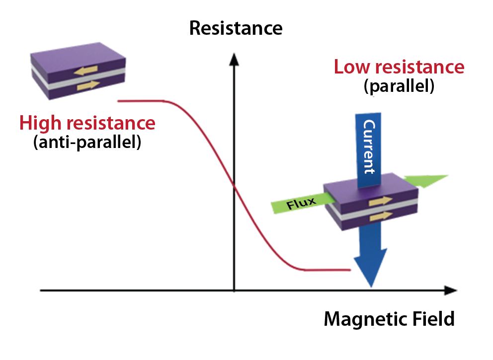
The electrons moving within the free layer and pinned layer planes are unable to cross the spacer layer to the opposite side. However, if magnetic flux is applied to the MTJ, the magnetism direction of both ferromagnetic layers can be switched between anti-parallel and parallel orientation. In the parallel magnetism orientation, electrons can make a quantum leap to tunnel through the spacer layer; a tunneling current will be observed across the MTJ structure and the relative resistance of the MTJ will be changed between high resistance and low resistance.
The difference of relative resistance is the “TMR ratio” (Fig. 3 ).
TMR ratio = (Rap – Rp) / Rp
where
Rap = resistance of anti-parallel orientation
Rp = resistance of parallel orientation

Fig. 3: Tunneling magnetoresistance mechanism and TMR ratio formats
The TMR ratio can reach approximately 40% at room temperature, and it is comparatively larger than other MR technologies. This feature, which is an implementation of quantum physics, makes the TMR sensor possible, with higher sensitivity, lower power consumption, and more stable characteristics.
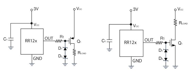
When designing with a TMR sensor, there are three very simple ways to implement a power-on circuit. The first is to connect the push-pull output to a wake-up pin on the microcontroller. The second is to connect the open drain output directly to the IC you want to power; this method is restricted to the maximum current that a TMR sensor can sink, which is 20 mA. For higher currents, a third method can be utilized: connecting the sensor output to MOSFETs. This can be done to implement normally open and normally closed operation (Fig. 4 ).

Fig. 4: Normally open design with P-channel MOSFET (left) and normally closed design with N-channel MOSFET (right)
Advertisement
Learn more about Electronic Products Magazine


