Serial interfaces yield miniaturization and low cost
A look at the dozen different serial interfaces integrated into microcontrollers
BY ALEX MARTINEZ
Microchip Technology
Chandler, AZ
http://www.microchip.com
A popular means of reducing size and cost for any embedded design is to use a communication bus with fewer I/O pins. Moving from a parallel bus to a serial bus provides significant size and cost reductions. Moving from one serial bus to another with fewer pins can also be beneficial in designs where small size is the key parameter.
Speed is often a critical parameter, so it will play an important role in making a serial bus selection. There are over a dozen different serial interfaces integrated into MCUs, and this article will explore the pros and cons of each.
USB vs. FireWire in PCs
One popular bus that drove a major change in the PC market was USB (universal serial bus). Its high speed, low pin count, and versatility encouraged its use, and USB has pretty much replaced the parallel printer and RS-232 serial orts. USB 2.0 also won out against FireWire S400 because of lower system costs.
Additionally, USB can rely on the host processor’s use of PC resources to manage low-level protocols, while FireWire delegates this to its interface hardware. This additional hardware cost and the initial FireWire license fee enabled USB to emerge as the interface of choice in the PC world and lead to the rapid adoption of USB in embedded applications.
Synchronous vs. asynchronous interfaces
When selecting a serial interface, both synchronous and asynchronous interfaces should be reviewed. Synchronous interfaces use a master clock for synchronization; asynchronous interfaces embed the clock into the data stream. Frequency variations of slave-device clocks do not affect synchronous interfaces, so lower-cost oscillators can be used. In asynchronous devices, synchronization requires an agreement on the transmission speed, protocol, frequency of resynchronization, and clock stability from all devices.
Synchronous interfaces enable easy interdevice connections on the same PCB, while asynchronous interfaces are designed to connect systems using cables that are a few meters up to a kilometer apart. Applications range from simple point-to-point connections to complex networks with hundreds of devices. The different physical interfaces for each bus type can also be described by the OSI model.
OSI seven-layer model
Synchronous interfaces typically support the data link layer (layer 2) and the physical layer (layer 1) internally, while most asynchronous interfaces support the data link layer internally and the physical layer externally. On occasion, the asynchronous interface supports both layers internally. For some applications, the same data link layer is combined with different physical-layer drivers to create different interface standards. In a microcontroller, layers 3 to 7 are typically implemented in software with some hardware support.
Moving from a parallel to a serial interface
When system software requires large amounts of memory, a microcontroller with an external address and data bus is usually selected. With 16 or more I/O pins needed for parallel flash program memory and SRAM, designers have the option of using a microcontroller with internal memory to preserve I/O pins, reduce size and lower costs. Many microcontrollers now come with increased program memory densities, but when the amount of internal memory is not sufficient, the use of external flash program memory or serial SRAM using an SPI port can be employed.
Serial flash program memory and serial SRAM devices are offered only with the SPI bus, so selecting this bus enables the most efficient system design. When components are offered only in a specific bus they determine the bus selection, except when a single-wire device would provide a better solution.
Synchronous Interfaces
SPIMicrowireI2CUniversal Serial Asynchronous Receiver Transmitter (USART), synchronous & asynchronous modes
Criteria used in serial bus selection:
1. System components only offered in one bus type
2. Available bus drivers on the MCU
a. SPI & I2C, or synchronous serial
port (SSP)
b. Serial control interface (SCI)
c. USART
d. GPI/O with software drivers
e. Other network buses
3. Bus speeds required
4. Low pin-count bus for small size
5. Push/pull or open drain outputs
6. Overall system cost
7. Feature set offered
The SPI bus supports typical speeds ranging from 5 to 20 MHz, but also up to 75 MHz for high-speed serial flash program memory. The Microwire bus is similar to the SPI bus in operation and number of connections, but the bus specification limits its communication speed to 3 MHz.
The I2C bus has clock and data lines, is software addressable and has a typical operating speed of 400 kHz, with many devices capable of 1 MHz. Since microcontroller I/O ports are often in short supply, the fewer ports needed are a big advantage. The SPI and Microwire buses typically use four I/O ports, while the I2 C bus uses two.
The next move in miniaturizing a system is to look at even smaller buses that use a single I/O port. Since this can only occur by embedding the clock in the data stream, these interfaces must be asynchronous.
Asynchronous Interfaces
Today, there are two different asynchronous buses competing for sockets that are usually reserved for synchronous buses. These buses are the 1-Wire Bus (Maxim) and the UNI/O Bus (Microchip Technology).
Devices on the 1-Wire Bus are housed in a 2-pin package, with one pin for ground and the second pin for data and power. A capacitor is designed into the 1-Wire device to allow parasitic power to be extracted from the data line. Using an open-drain output, speeds up to 16.3 Kbits/s can be obtained with a 5-kΩ resistor, and decreasing the value to 2.2 kΩ increases speeds to 142 Kbits/s.

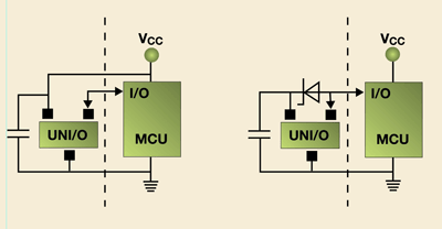
Fig. 1. UNI/O serial interface circuits
The UNI/O Bus is a new single-wire bus standard that is housed in a 3-pin package to support power, ground and data connections. Manchester encoding is used for communications, to support data rates from 10 to 100 Kbits/s. This bus was designed for standard embedded designs, but adding an external Schottky diode and adjusting the value of the bypass capacitor allows it to be used in applications with a 2-pin interface. The block diagrams in Figs. 1a and 1b show how simple this solution can be.
The oldest and most predominant asynchronous interface is the UART, also called a USART when both synchronous and asynchronous modes are required. Referring back to the OSI model, the UART onboard the MCU implements the data link layer, while the physical layer is covered by several driver standards. The most popular among these standards are RS-232C/422/485 interfaces.

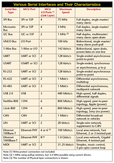
Table 1 presents a summary of various serial interfaces and their characteristics. There are also plenty of microcontrollers with asynchronous interfaces that are designed for networking, such as Ethernet, CAN, LIN and MIDI. Their complexity is beyond the scope of this article, but they are referenced in the table. ■
Advertisement
Learn more about Microchip Technology


