Silicon MEMS oscillators as an alternative to legacy quartz
Designers are increasingly turning to new silicon timing devices because of several inherent technical and business advantages
BY STEVE PRATT
Director of Marketing
SiTime
www.sitime.com
The timing component is the heartbeat of electronic systems and it can have a significant impact to the performance and reliability of the system. Today there are three main reference-clock oscillator choices for modern electronic systems — quartz oscillators, silicon oscillators without a resonator (LC based), and MEMS resonator-based silicon oscillators. Even though quartz technology has been successfully deployed for over 60 years, more advanced silicon timing solutions have started to replace quartz products in all application segments.
Quartz vs. silicon timing solutions
Quartz has been the predominant technology of choice for timing references. A quartz oscillator consists of a piezoelectric crystal, along with an analog circuit, in a ceramic package. It provides accurate and stable clocks that meet the requirements of most electronic applications. However, it has many inherent limitations, such as limited frequency, supply voltage and pull range options, as well as long lead times and lack of easy availability.
100% silicon alternatives: MEMS vs. LC
A MEMS oscillator relies on a MEMS resonator as a precision reference, while a LC oscillator is self-referenced. The benefit of the LC oscillator is that it is very inexpensive; the disadvantage is that it has lower performance than a MEMS oscillator. The MEMS-based silicon solution consists of two pieces of silicon—the MEMS resonator and the analog CMOS IC, both of which are co-packaged in cost-effective plastic packages. MEMS oscillators easily provide 10-ppm stability over the industrial temperature range, while LC oscillators are typically 10 times worse, at 100 ppm. Applications such as USB 2.0 can use LC oscillators, while networking and storage applications typically use MEMS or quartz oscillators.
Frequency stability over temperature for oscillators
Quartz oscillators have difficulty in achieving 25-ppm stability over the industrial temperature range and require additional testing or screening that increases cost. Figure 1a shows the difficulty in using quartz to


Fig. 1: Quartz stability (a) vs. MEMS stability (b) (Note the scale on Fig. 1b: ±5 ppm)
Temperature-compensated oscillators (TCXO)
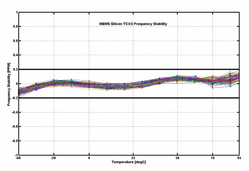
TCXOs are typically used in applications that require frequency stability of less than 5 ppm. In these applications, temperature range is often traded off for increased stability. Many consumer applications such as mobile phones, e-readers, and tablets can accept a narrow temperature range such as 10 to +70°C and need frequency stability for wireless synchronization down to 0.5 ppm. Newer applications such as small-cell and base station applications require stability down to 0.2 ppm, necessitating the use of an oven-controlled oscillator (OCXO). MEMS TCXOs have reached OCXO-level performance. Figure 2 shows MEMS TCXO frequency stability over the 40° to 85°C temperature range.

Fig. 2: Silicon MEMS temperature-compensated (TCXO) stability
Frequency range
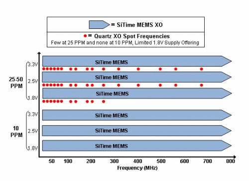
MEMS oscillators are typically programmable, and can offer any frequency and features within the operating range. Due to manufacturing limitations, quartz oscillators are only available in “spots,” that is, limited product offerings, which cannot be customized to the customer’s requirements.

Fig. 3: Quartz oscillators are available only in spots.
Figure 3 illustrates the limitations of quartz to offer
Jitter performance
Jitter is one of the main contributors to system timing errors. All clock designs must account for the oscillator’s jitter to make sure their timing budget is not exceeded. Jitter requirements vary by application. For example, processors and parallel communications such as DDR2/3 require anywhere from 4psRMS to 100psRMS. The jitter contribution from the reference oscillator ideally must be an order of magnitude lower. Serial communications such as 10GbE, FibreChannel, and XAUI have a jitter budget from 1ps up to 5 ps, integrated over 12-kHz to 20-MHz offsets. MEMS oscillators are available that meet all these different jitter requirements.
Low-EMI applications
Often, after the system design is complete, emissions need to be reduced to meet environmental compliance. The clock signal can be used in the following ways to reduce EMI:
1. Spread spectrum
2. Slower output edge rates
Legacy quartz oscillators do not generally supply spread spectrum or drive strength flexibility. If an application requires slower edge rates or spread-spectrum modulation of the clock signal, the SiTime MEMS oscillators offer these functions as standard options with pin-compatible footprints. These options can help meet environmental compliance without expensive or time-consuming design or layout changes.
Tunable (pullable) oscillators (VCXO)
Some applications require tuning of the oscillator’s output frequency within a few hundred parts per million. Many XOs and TCXOs have the option for tuning, and are called voltage-controlled XO (VCXO) and voltage-controlled TCXO (VCTCXO). Today’s crystal-based VCXOs provide up to 200 ppm of pulling range (tuning range). A VCTCXO provides much less pulling range, typically around 15 to 25 ppm. Designers of applications that can benefit from a larger pulling range have been forced to consider other alternatives such as adding a PLL synthesizer or multiplexing multiple oscillators at different frequencies into the clock path. However, SiTime’s MEMS VCXOs and VCTCXOs provide a new level of tuning range up to ±1,600 ppm. These extremely wide pulling range enables new clock architectures that significantly simplify clock designs. For example, the video processor within a TV or a monitor may need to accept multiple video standards coming in another source such as a DVR. Video processing applications typically operate under two video clock frequencies—74.25 MHz and 74.175 MHz. A SiTime MEMS VCXO with ±1,600-ppm pulling range enables a single VCXO to be used instead of two VCXOs or a PLL synthesizer.
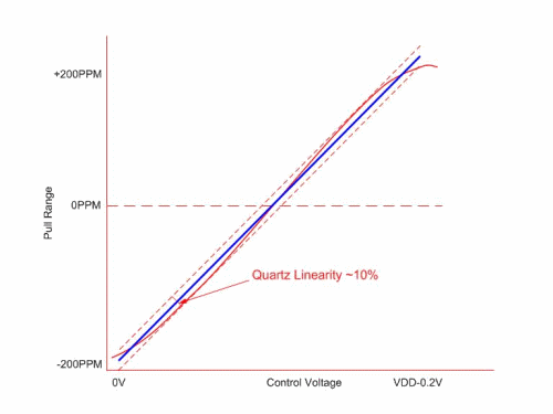
Another important parameter is the linearity of the tuning range. Tuning range linearity is the deviation from the ideal across the entire tuning range. Typical VCXO linearity is only 10%, which means the system must add additional overhead to compensate from the linearity error. MEMS VCXOs and TCXOs available today have 10-times better linearity than the quartz-crystal alternative, as shown in Fig. 4 .

Fig. 4: MEMS tuning range linearity vs. quartz
Digital input control (DCXO)
For applications that directly interface to a digital control, there are few options available from quartz-crystal oscillator suppliers. VCXOs and VCTCXOs interface to an analog voltage for tuning control, requiring either a digital-to-analog (DAC) in the control path or a PWM modulation scheme. SiTime offers the traditional voltage controlled oscillator, but also offers a digital input, thus allowing a direct digital interface to the ASIC or SoC (Fig. 5 ). Improved jitter performance is an additional benefit with the digital interface of a MEMS-based VCXO or VCTCXO because noise from the internal analog-to-digital converter (ADC) is eliminated.

Fig. 5: MEMS silicon digitally controlled oscillator (DCXO)
Availability
Availability is almost as important as performance and flexibility when selecting an oscillator. Many different oscillators are offered, however less than 5% are generally held in stock because each quartz oscillator configuration has to be manufactured separately. Conversely, SiTime silicon oscillators are delivered on demand. The company uses batch manufacturing and semiconductor industry flow. In addition, inventory is held in die bank and finished blank package form. As a result, samples can be easily turned around in a matter of minutes and custom products are delivered in 2 to 4 weeks.
Reliability
A quartz resonator has many different modes of operation and can operate at different frequencies. If the analog circuit is not designed correctly, then it can lock to an incorrect mode of operation. This results in an incorrect frequency in the system, which can then result in failure. Such modes can happen at different operating voltages, temperature ranges, shock and vibration conditions, and also over time.
Quartz also suffers from activity dips. At different temperatures, the operating frequency of quartz can change and cause a corresponding frequency shift of several parts per million. An application that uses a 25 to 50-ppm XO will not see the activity dip, even though it may be occurring over temperature. However, an application using a 0.5 to 2.5-ppm TCXO will be affected by an activity dip, resulting in system failure. Activity dips are very unpredictable and vary from one lot to another. Because silicon MEMS oscillators do not have activity dips, they are a 100% safe alternative.
For more than 60 years, quartz oscillators have been used in electronic equipment. Over that time, quartz oscillators have remained a very good product but they suffer from major issues in performance, supply chain and reliability. Today, designers are increasingly turning to new silicon timing devices because of several inherent technical and business advantages. ■
About the author
Steve Pratt holds the position of Director of Marketing at SiTime. Steve has been in the semiconductor business for more than 20 years and prior to SiTime, has worked for various analog semiconductor companies including Maxim, Micrel, and Monolithic Power Systems. Steve holds a BS degree in Industrial Engineering & Technology.
Advertisement
Learn more about SiTime


