BY MANFRED BRANDL, Product Manager, Automotive, ams, www.ams.com/eng
Today’s typical battery management system (BMS) captures individual cell voltages in a time-deterministic way and communicate them to a powerful host controller. Comprehensive datalogging and software functions then perform the required computations for cell diagnosis, functional safety, state of charge (SoC), state of health (SoH), capture, and balancing decisions.
The problem is, this standard approach is complex and costly. That’s because the main cost drivers in the standard approach require electromagnetic compatibility (EMC) robust communication architecture across voltage domains, a multitude of highly accurate measurement systems, a powerful host controller, the development and qualification of complex software in a safety critical system, and redundancy for functional safety.
Late start, fresh ideas
Sometimes, entering a market as a latecomer brings about new ideas and new means for accomplishing the same goals. That’s precisely what happened when ams entered the battery cells supervising electronic market. The company took a different tack for correcting the challenges outlined by the electric-vehicle (e-vehicle) automotive community. When the automakers reported severe difficulties in fulfilling battery management requirements with the existing products on the market, it provided an opportunity to rethink the entire subject from a different perspective.
The new approach does not follow the standard OEM requirement specs, but instead focuses exclusively on the difficulties facing battery manufacturers and battery management systems (BMS) electronic system integrators. An application-specific standard product (ASSP) was developed with funding support from two European Union research projects: e3car and Estrelia.
What is different?
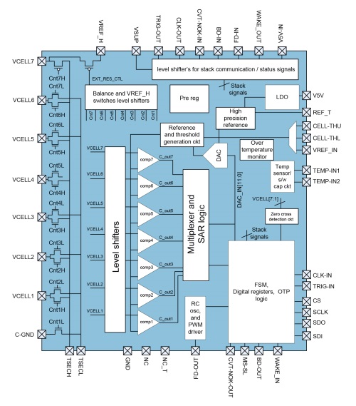
• The new approach (see Fig. 1 ) mitigates the communication issue throughout voltage domains and reduces software complexity by moving most of the functionality from the host controller to the local monitoring / balancing integrated circuit.
• There are extraordinary accuracy demands when balancing lithium iron phosphate (LFP) chemistry cells at an intermediate SoC — or even full SoC specifications — to achieve long battery life. This was addressed by a simultaneous comparison of all cells in a stack with accuracies as good as 1 mV. Thus, accuracy demands are met and EMC robustness is strongly enhanced by the simultaneous capture. This also opens new features to balance under low load and toward end of charge.
• The new approach works with low balancing currents because the origin for accumulative misbalance over time is dominated by differences in quiescent consumption of the supervising electronic itself (in the low milliampere or microampere range). This ensures long battery life, as cells are not additionally exercised by large balancing currents. It also helps avoid power dissipation and heat generation (which age cells), and mitigates the occasional possible incorrect balancing decisions due to noise or unknown temperature of cell cores.
This disruptive BMS approach — with these attributes built into an IC that can support up to seven cells — is now available in the market.

Fig. 1: The block diagram of the ASSP.
Demo hardware was developed that shows a minimum solution for cell balancing and cell monitoring that works on its own, with no micro controller needed.
How it works
The IC offers a high-accuracy reference output REF_T of 4.5 V to be used by external precision resistive dividers or temperature sensors. ams demonstrated the capability by using a 4.5-V REF_T pin to generate 3.55 V as the maximum cell voltage for LFT cells. This 3.55-V reference is connected to the VREF_IN pad as a reference for internal comparators.
Seven battery cells are connected to the respective channels (VCELL1 to VCELL7) of the IC. One discharge resistor of 20 Ω is connected to TSEC1 and TSEC2 pins. Balancing is triggered by a pushbutton and stored by a latch to provide the signal to TRIG_IN. Next, monitoring and passive balancing begins. Cells are monitored against a maximum and minimum cell voltage range as provided to the CELL_THU and CELL_THL; cell voltages are compared to the VREF_IN at 3.55 V.
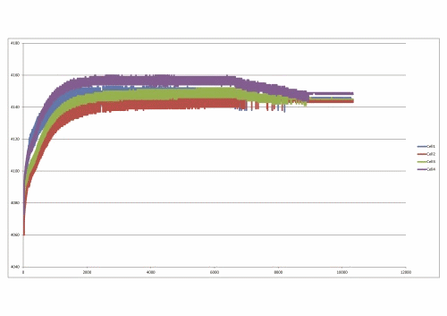
When cells are charged in constant voltage phase and the first cells begin exceeding 3.55 V, they are discharged through the integrated balance switched to meet the 3.55 V. When all cells have crossed the 3.55 V limit at least once, balancing ends.
This function is shown in the diagram in Fig. 2 for LIPO cells charged to 4.14 V.

Fig. 2: Balancing example during a constant voltage charge where LIPO cells are charged to 4.14 V
This process can be applied to each module of a large battery. The ICs can be chained and synchronized by a common clock and trigger-line driven by a micro, allowing the full battery stack perfect balance with no software and very little hardware effort.
Essentially, the slim-cell electronic consists of one ams AS8056 IC per seven cells, one discharge resistor and a few resistors that adjust reference voltages as a minimum to run the passive balancing function and diagnosis functionality. Together, they show that the voltages and temperatures are good and that the balance is complete.
The new device design also supports complex battery managment systems controlled by a micro, serial cell voltage and temperature readout, broadcast of digital references and to cover functional safety demands. Additionally, an EMC robust daisy chain communication concept was developed and has undergone successful first e-vehicle system-level tests without bit error issues when the inverter and electric motor are running.
Because this new approach integrates balancer switches, the device also supports active balancing at low current levels. This new feature helps further increase efficiency and provides intrinsic module-to-module balancing due to the charge redistribution inside the pack.
Advertisement
Learn more about ams (formerly austriamicrosystems)


