This post sponsored by Texas Instruments.
Battery chemistries have and continue to undergo changes. While the simplest disposable cells are still viable for many designs, they do increase the cost of cell holders. Without an easy-to-replace battery, a more extensive battery swap is needed at a repair facility since most end users would not know how to unsolder and re-solder.
Cell holders also add to the overall size of the battery, but additional height, width, and length are not too disconcerting. Keeping access to detent tabs and space to swap a battery is a key part of enclosure design, and one that remains a concern for electronics designers.
It used to be that even rechargeable batteries needed replacing, but the extended number of charge cycles allowable while still maintaining capacity has made it possible to hard-mount rechargeable batteries for the life of the product. If this scenario applies to your designs, it is important to pay special attention to the battery-charging technology you utilize. Not all batteries or chargers are created equal.
This is not a trivial issue. Even automotive and aircraft engineers have come across issues with the implementation of a battery box that is based on the latest Lithium-ion technologies. This drives home the fact that a solid battery-management system is necessary, going above and beyond a simple battery charger.
Issues worsen when stacks of cells are mounted together and sealed. The characteristics and state of each cell should be carefully monitored since one defective battery can spoil the whole system. This explains why many designers are electing to mount smart-charge controllers with each cell. Once mounted as part of the cell, temperature sensing is more accurate on a cell-by-cell basis.
Each battery manufacturer has their ideal situations for charging. The battery algorithms are tailored for a specific battery with a specific chemistry. Even swapping the same cell from different manufacturers may pose a major problem in some instances.
The lowest cost battery chargers use very little silicon. They are dedicated to a particular battery, and are not flexible or programmable. Additional features and functions add silicon, cost, and size, and with these parts, it’s all about the yields per wafer.
More flexibility comes into play when cell chargers are programmable. When charge voltage and current can be precisely controlled, better performance and life can be expected, as long as the algorithms are correct. Here is where flexibility can be a big benefit.
For example, take the Texas Instruments™ BQ24195 Single Cell Charger IC. Optimized for fast and cool charging, the synchronous buck-mode fully integrated charger can deliver up to 4.5 Amps for Lithium-ion and Lithium-polymer single-cell batteries. The adjustable charge current aids software-controlled algorithms in optimizing the rate and temperatures at which each cell is charging.
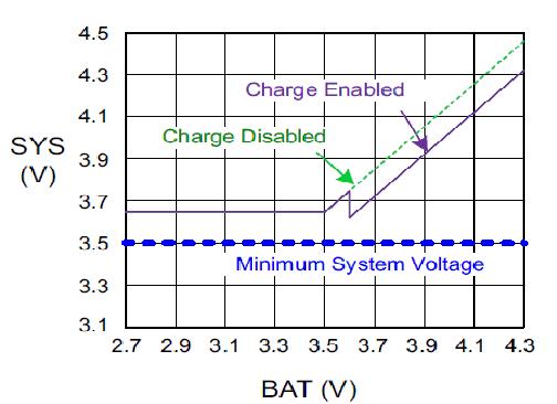
Parts such as TI’s bq24295 feature dynamic-power management (Figure 1) and use a switch-mode buck charge-control technique to efficiently take in up to 6 V (ideal for USB-based chargers), and deliver a programmable voltage with up to 3 A, while providing overvoltage protection and battery-temperature monitoring.

Figure 1: Dynamic charge control allows hysteresis-like operations of both LDO mode and boost modes of charging to assure battery voltage never drops below a minimal system voltage. (Source: Texas Instruments)
Fine tuning requires a microcontroller and an interface. In order to keep pin counts low, an I2C interface allows all access and control of the cell. It is important to note that even if the micro switches off, these parts will maintain battery charging without host management.
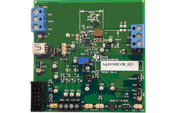
A Battery Charger Solutions Overview can help inform options and techniques at the designer’s disposal. Also, to help test designs in a design or lab environment, the bq2419x Adapter Charger Evaluation Module is available (Figure 2) from Texas Instruments. This evaluation module demonstrates the single-input USB-compliant charge-control technique using a 1.5 MHz switching frequency. Many designers prefer this because it can be used with audio designs and not cause any audible noise.
Other Battery Management Guides from Texas Instruments can shed more light on the subject, and information to aid in the design of Faster Charging Systems for Power Banks is also available.
A complete reference design with schematics, PCB layout, BOM, and references can be found here. In addition, development tools to help test and evaluate this technology can be found here.

Figure 2: Low-cost evaluation kits demonstrate fast charging with up to 92 percent efficiency using I2C to control single-cell charging. These kits provide overvoltage protection and allow design engineers to monitor the temperature of each cell. (Source: Texas Instruments)
BQ24195
For more information about this product, click here.
To request a sample, click here.

To buy now at Mouser, click here.
BQ24295
For more information about this product, click here.
To request a sample, click here.

To buy now at Mouser, click here.
BQ24261
For more information about this product, click here.
To request a sample, click here.

To buy now at Mouser, click here.
BQ24610
For more information about this product, click here.
To request a sample, click here.

To buy now at Mouser, click here.
BQ24251
For more information about this product, click here.
To request a sample, click here.

To buy now at Mouser, click here.
BQ24650
For more information about this product, click here.
To request a sample, click here.

To buy now at Mouser, click here.
BQ51025
For more information about this product, click here.
To request a sample, click here.

To buy now at Mouser, click here.
By: Jon Gabay, Hearst Business Media
Advertisement
Learn more about Texas Instruments


