By Cary Delano, Distinguished Member of Technical Staff, and Gaurav Mital, Principal Member of Technical Staff, Mobile Solutions Business Unit
Maxim Integrated
www.maximintegrated.com
It goes without saying that the smaller the device, the smaller the battery that it can support. Yet this doesn’t mean that consumers expect their wearable or hearable product to be short on battery life. Therein lies the design challenge: Small electronic devices powered by Li+ batteries must run reliably for long periods between charges, while, at the same time, their power supplies must support the distinct and diverse voltage requirements of the sub-systems within the design. An optimal solution is the single-inductor, multiple-output (SIMO) power converter architecture, which integrates functionality that would otherwise require multiple discrete components.
Looking at a traditional multiple switching-regulator topology, we can see that each output voltage has its own switching regulator that needs a separate inductor (Fig. 1 ). The approach isn’t ideal for small products, though, as inductors are physically large and costly. Another architectural option is the linear regulator — these are compact, fast, and low-noise, though they do have a higher power dissipation.
Sometimes, though, you can’t avoid having an inductor in the system. While small, an LDO can never provide a boost feature on its own. This suggests yet a third approach, a hybrid of sorts using multiple low-dropout regulators (LDOs) in conjunction with DC/DC converters. This configuration would result in intermediate power and heat dissipation, although it would also produce a larger design than LDOs alone.
Buck-boost SIMO converter

Fig. 1: Traditional architecture for a buck-boost switching regulator.
A buck-boost SIMO converter, on the other hand, can regulate up to three output voltages over wide output voltage ranges via a single inductor. When all of the output voltages are less than the system supply battery voltage, a buck-only SIMO architecture would appear to work. As one or more output voltages approaches the input voltage, however, a weakness of the buck-only SIMO becomes apparent. When an output voltage approaches the battery voltage, a buck-only SIMO would require the inductor for too much time, impacting the other channels. The buck-boost topology calls for less time as a buck-only SIMO to service each channel, which results in better utilization of the inductor. Also, because the SIMO architecture requires only one inductor, solutions that need at least one boost voltage are almost always better with a buck-boost SIMO. See Fig. 2 for a block diagram of the SIMO architecture.
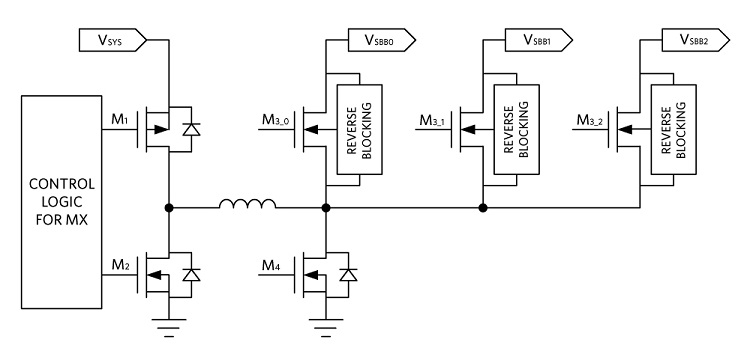
Fig. 2: SIMO architecture block diagram.
Using a design that uses only a single inductor helps keep supply size down, but there is more to be gained with the buck-boost SIMO approach. A key design parameter is saturation current (Isat), which is a measure of electrical current involved when the inductance drops to 70% of its value. The value of Isat is determined by the inductor’s core size for a given core material and construction, so minimizing the requirement on Isat further helps reduce supply size and cost. Compared to using separate DC/DC converters, then, using a single inductor in a SIMO architecture provides many benefits:
- Better utilization of Z-height, when allowed by the system
- Improved cost savings and footprint
- Time multiplexing, which arises when different features are often not used simultaneously. You’ll see this advantage when the total supply current is less than the sum of the individual output requirements. For instance, consider when you’ve got system events that happen sequentially, each using different rail voltages, such as data in a Bluetooth system being fully downloaded before the system activates a function. In such a case, the power associated with the radio is on at different times than the activated function(s). So, the total Isat required for the SIMO inductor(s) used can be less than required for separate converters.
- RMS (current rating for inductors) — The channels are not time-multiplexed, but the peak power consumption of all features often doesn’t happen simultaneously, which can lower the total inductor Isat requirements.
SIMO architecture tradeoffs — how to address them
As with many approaches, even a SIMO architecture has its tradeoffs, which makes a thoughtful approach to the design essential. For example, because a single inductor is essentially providing buckets of energy to alternate outputs, the output voltage ripple will tend to be on the higher side. What’s more, because a SIMO is heavily loaded, it becomes time-limited and there can be delay in servicing each channel, which can further increase output voltage ripple. Using larger output caps will help offset these sources of output voltage ripple while maintaining a net footprint/BOM advantage.
Power management ICs (PMICs) designed with micropower SIMO buck-boost DC/DC converters can thus provide a good solution for extending battery life in small electronic devices, such as wearables and hearables. By utilizing the whole battery voltage range, as each output has the benefit of being a buck-boost configuration, such converters can create output voltages that are above, below, or equal to the input voltage. With a feature such as programmable peak inductor current for each output, you can optimize the balance between efficiency, output ripple, electromagnetic interference (EMI), PCB design, and load capability for your design.
Such PMICs are now becoming available. For example, two new PMICs from Maxim — the MAX77650 and MAX77651 — were designed with micropower SIMO buck-boost DC/DC converters. These PMICs always operate in discontinuous conduction (DCM) mode; as such, the inductor current goes to zero at the end of each cycle to further minimize crosstalk and prevent oscillation. A proprietary controller in the SIMO control scheme in these converters ensures that all of the outputs get serviced in a timely manner. When no regulators need service, the state machine simply rests in a low-power rest state. When the controller notices that a regulator needs service, it charges the inductor until it reaches the peak current limit. Subsequently, the inductor energy discharges into the associated output until the current reaches zero. In the event that multiple output channels require servicing at the same time, the controller ensures that no output utilizes all of the switching cycles. Instead, the cycles interleave between all of the outputs that require service, skipping those outputs that don’t need service.
Power comparison: SIMO vs. conventional architecture
As an example of how SIMO buck-boost converters perform when using a SIMO-optimized PMIC, Fig. 3 depicts a block diagram of the MAX77650 power tree. Three of the four loads connect to the Li+ battery via the high-efficiency SIMO switching regulator. The fourth load is powered by the PMIC’s integrated LDO, drawing from the 2.05-V SIMO output and achieving 90.2% efficiency (1.85 V/2.05 V). Table 1 provides a comparison of the power performance between a conventional architecture and the SIMO architecture in this example. Developers seeking to run their own performance tests on the SIMO architecture can use evaluation kits that are available for both the MAX77650 and the MAX77651.
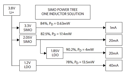
Fig. 3: MAX77650 power tree with each regulator’s output voltage, load current, efficiency, and power dissipation.
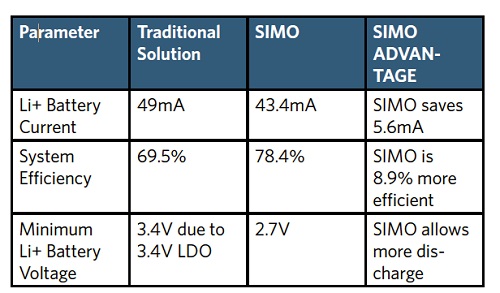
Table 1: Power performance of SIMO architecture versus conventional architecture.
Consumers want to be able to rely on their small, battery-powered electronic devices to operate for long periods of time between charges. Because these devices are small, however, they are obviously limited in the battery capacity that they can support. For ultra-low-power, space-constrained applications, PMICs integrated with SIMO switching regulators can extend battery life while also reducing component count and limiting the need for bulky inductors.

Gaurav is the Power Architect for high-performance computation-intensive PMIC and advanced low-power PMIC product lines at Maxim Integrated. He started his career as an analog power design engineer and worked on a broad range of innovative mobile power products through the years. He received his B.S. in EE from Mumbai University, India, and M.S. degree in EEE from California State University, Sacramento.

Cary has worked in the semiconductor industry for over 25 years and is an inventor for over 40 issued U.S. patents. Cary is one of the original “fathers” of audio class D, leading the design of the first commercial audio class D amplifier (Tripath TPA2020). Cary also founded two startups with successful exits and was also the first employee at Tripath, where he was a VP. Cary has an MSEE from Santa Clara University.
Advertisement
Learn more about Maxim Integrated


