Despite MIMO and STC’s multichannel nature, many useful, important measurements can be made with a single-input analyzer
BY BEN ZARLINGO and PETER CAIN
Agilent Technologies
Santa Clara, CA
http://www.agilent.com
WiMAX Wave 2 adds multichannel transmission schemes in the form of space time coding (STC) and multiple-input/multiple-output (MIMO), and it is often assumed that multi-input analysis capability is required to characterize the performance of these multichannel transmissions. In practice, many useful and important measurements such as channel isolation and frequency response, along with most traditional RF parameters can be made using a single-input analyzer. The large number of pilot tones and the unique association of the pilots to each transmitter, in particular, enable many of the single input measurements described in this article.
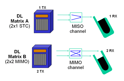
Fig. 1. Matrix A (STC) and Matrix B (MIMO) implementations for WiMAX Wave 2 single- and dual-input analyzer measurements.
Matrix A (STC) and Matrix B (MIMO) are two downlink transmission schemes included in WiMAX Wave 2, for spatial diversity and spatial multiplexing, respectively. As shown in Fig. 1 , Matrix A is a 2×1 STC antenna diversity technique that uses two transmit data paths, Tx0 and Tx1, at the Base Station (BS) and a single receive path, Rx0, at the Subscriber Station (SS). Matrix A implementations transmit each data symbol from both antennas with different coding, improving the ability of the receiver (which has knowledge of the coding) to properly demodulate the signal in difficult conditions.
To achieve higher data rates, WiMAX Matrix B implements a MIMO scheme with two or more transceivers on both the BS (base station) and SS (subscriber station) ends. Using a 2×2 version of Matrix B MIMO as an example, the user data to be transmitted is divided between two transmit antennas, operating on the same frequencies simultaneously. Two (or more in the case of diversity schemes) antennas are used at the receiver end, and the resulting signals are the result of four effective signal paths as shown in Fig. 1 . In practical situations the four signal paths will have different amounts of correlation and this correlation will vary by frequency or subcarrier, though some degree of independence is required for proper MIMO functioning. The goal of signal processing in a 2×2 MIMO system is to measure or characterize the 4 transmission paths and to “reverse” this measurement to separate the signals transmitted by the two transmit antennas. A related MIMO configuration can also be used in the uplink (UL) where single channel transmitters coordinate their transmissions for MIMO operation, but such “uplink collaborative MIMO” is beyond the scope of this article. [1]
Single and dual-input analyzers can provide a variety of important measurements on WiMAX Matrix A and Matrix B configured systems. Basic RF characteristics such as frequency, power and timing can be measured at different points within the RF path from the transmitter to the receiver. Most measurements are made with a direct connection to the circuit (rather than with an antenna), just as they are for traditional single channel systems. For example, the quality of either single transmitter channel (typically referred to as Tx0 and Tx1), as shown in Fig. 1 , can be made using a single-input analyzer connected directly to the selected transmitter output. Of course a two input analyzer could measure basic RF characteristics for two transmitter channels simultaneously, but a practical approach in most cases is simply to change the measurement connection and repeat the measurement.
Perhaps surprisingly, measurements from a single directly-connected analyzer input can also be used to measure essential MIMO/STC parameters such as channel frequency response and channel-to-channel isolation (crosstalk), even when both transmitter channels are actively sending data. An even more novel technique is to combine the transmitter signals and then measure the precise cross channel timing and phase relationship. Such measurements are made possible by the non-overlapping pilots in WiMAX, as we will describe here.
Non-overlapping pilots
In all STC and MIMO system configurations, downlink data is recovered at the SS with some knowledge of the channel. The effective transmission channel (modeled as two complex transfer functions in Matrix A, and four in a 2×2 Matrix B configuration) is estimated using pilot carriers spread across the channel bandwidth. In contrast to other OFDM schemes such IEEE 802.11a/g/n (wireless LAN), the number of pilots is much larger and the pilots typically change frequencies for every symbol. A critical factor to appreciate is that each of the two transmitters uses only half of the available pilot carriers, transmitting (ideally) no energy on the pilot carriers of the other transmitter. The pilot carriers are thus sometimes described as being transmitted “in the clear.” Data carriers, on the other hand, are used simultaneously by both transmitters.
This pilot structure allows the two transmit channels, whose RF characteristics are generally represented by their respective pilot carrier sets, to be separated and measured, even with a single analyzer input. The analyzer simply needs to know, for any given symbol, the intended pilot carrier set, and to be able to resolve and measure the individual carriers.
A simplified conceptual timing and subcarrier example for a two-channel transmitter is shown in fig. 2 . In this figure, at symbol time n+1, the first transmitter, Tx0, transmits a pilot subcarrier, two data subcarriers and a null subcarrier. Simultaneously, the second transmitter, Tx1, transmits a null subcarrier, two data subcarriers and a pilot subcarrier over this same symbol time. In the ideal case, a pilot subcarrier in one transmitter channel does not overlap any frequency subcarrier in the other channel. If there is some level of crosstalk between the two transmitter channels, a signal analyzer can measure it as pilot energy appearing at the time and frequency of the anticipated null subcarrier.
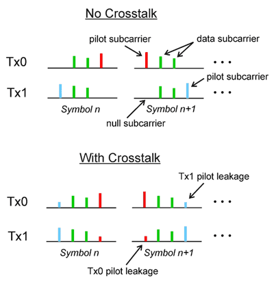
Fig. 2. Pilot and data subcarriers over 2 symbol times in a dual-channel transmitter. Note the crosstalk appearing as pilot leakage between the channels.
Figure 2 also shows the subcarrier distribution for a system when crosstalk is present. In this example, the measurement for the leftmost null subcarrier for Tx1 at symbol time n+1 includes pilot energy resulting from the crosstalk from Tx0. These non-overlapping pilot subcarriers provide a unique measurement approach for determining the level of crosstalk between the two transmitter channels. As shown in the next example, by measuring the transmitter output directly at Tx1, the pilot leakage from Tx0 (and that of the opposite case as well) can be determined.
Example cross-channel measurements
As previously described, the pilot structure of the WiMAX Wave 2 signal allows for convenient single-ended, single-channel measurement of the crosstalk between the two transmitter channels. Fig. 3 shows two measurement examples in the form of the Agilent 89600-series VSA software’s “OFDM MIMO Info” table. The measurements are made with the analyzer configured as a single receiver Rx0 (using the software with a single input spectrum/signal analyzer, for example), directly connected to transmitter output, Tx0, and measuring a Matrix B signal. In this case, the single-input analyzer reports the Tx0 pilot power (the “PilotPwr” line in the table) as measured at Rx0 (the intended pilot power transmission) as +15.6 dBm and the Tx1 pilot power measured at Rx0 (the incidental pilot power transmitted due to crosstalk) as -25.4 dBm. The difference between these measured power levels is a useful measure of the relative crosstalk, about -41 dB. Figure 3 also shows a second example with a crosstalk of 29 dB calculated from the measured Tx1 pilot power, now -13.4 dBm, and Tx0 pilot power at +15.6 dBm as before. Similar results would be obtained if the analyzer was directly connected to the second transmitter Tx1, and measuring Tx0 pilot power instead. Remember that the analyzer knows which transmitter should be sending pilot energy on any given subcarrier at a particular symbol time. Note also that additional table columns are available for other Tx/Rx combinations (only one is shown here, “Tx-/Rx-“) when a second analyzer input is available.
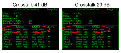
Fig 3. Measuring crosstalk or channel isolation using a single analyzer channel. The desired pilot power and the power from crosstalk are compared on the “PilotPwr” line of the tables.
The result of crosstalk between the transmitter channels is a distinctive pattern in the demodulated IQ constellation of the WiMAX waveform, especially apparent when measured directly at the transmitter output. Because the two transmitter channels (and indeed the individual OFDM subcarriers) are aligned in time and coherent in frequency and phase, the data subcarriers will coherently add when one transmitter channel couples to the other.
To examine this effect, measurements were made on the same two signals as the previous example. For conditions with low crosstalk, an isolation of abut 41 dB as shown in fig. 4 , the constellation is as expected with data and pilot subcarriers seen as 16-QAM and BPSK respectively. When the crosstalk increases (isolation decreases) to 29 dB, the data subcarriers exhibit a distinctive spreading of the constellation points as the leakage signals coherently add. The result is a smaller 16-QAM constellation in the place of each expected constellation point. This “constellation of constellations” is practically unique (especially when the miniature constellations are erect and stable) to the case of STC and MIMO signals with crosstalk between two active transmitter channels.
This I/Q measurement result is much different than would be observed for most impairments in OFDM systems, where the constellations usually exhibit a random-looking state spreading due various signal impairments[2]. A related distinctive feature of STC/MIMO signals in WIMAX OFDMA is also clear in these constellations: Note that crosstalk does not significantly distort the symbol locations of the BPSK pilots (shown in white in the constellation) because these subcarriers are designed to be non-overlapping.
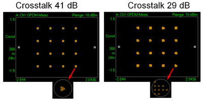
Fig. 4. Pilot and data constellation points at different levels of crosstalk from Tx1 measured at Rx0. One of the 16QAM data carrier constellation points is enlarged for clarity.
Single-input measurements can also be performed using an antenna instead of a direct connection to the transmitter. This allows some transmission channel effects to be examined, and may offer insight into the performance of diversity schemes. For Matrix A configurations, as shown in fig. 1 , the system performance is related to the amount of power received from each transmitter after transmission through the channel. In the ideal case, a measurement of the pilot power at a receiver input, say Rx0, from each transmitter, Tx0 and Tx1, should be approximately equal. Alternately, if the received power from one transmitter is dramatically lower, that channel may not provide sufficient spatial diversity and the overall system performance may degrade to that of a single-input/single-output (SISO) configuration. This single input approach of measuring pilots can also be used with Matrix B MIMO configurations where the transmission channel is stable, by sequentially measuring at each receiver antenna.
Single input measurements of frequency response
The large number of pilots and their non-overlapping structure, along with the ability of an analyzer to determine the transmitter channel associated with a particular pilot provide a straightforward way to measure the transmitter and/or channel frequency response with a single-channel analyzer. The indicated frequency response may provide useful insight into the nature of transmitter or channel problems. The measured frequency response is plotted vs. carrier number and is typically shown in terms of amplitude, phase, or group delay.
To measure Tx0 the analyzer can be connected directly to Tx0, which transmits the preamble for channel equalization and synchronization. To measure both channels (in a 2-transmitter system) one can connect both transmitter outputs directly to the analyzer through a power combiner, making use of the analyzer’s “Use Tx antenna” setting to specify the pilots from the desired channel to use for calculating frequency response.
The robustness of the information from the non-overlapping pilots is demonstrated by the ability of a single channel analyzer, directly connected only to Tx0 (no power combiner), to measure the frequency response of both transmitters in some situations. The key is to take advantage of crosstalk between the channels which provides measurable Tx1 pilot energy on the Tx0 signal, to which the single analyzer input is connected. With the analyzer configured (via the “Use Tx antenna” setting) to use only the Tx1 pilots the Tx1 frequency response is the result, as shown in fig. 5 . Note that the frequency response of Tx1 is similar to that of Tx0 but the measurement is considerably more noisy due to the limited amount of energy (-41 dB crosstalk in this example) from Tx0 that is present on Tx1.
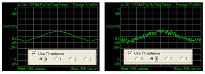
Fig. 5. The analyzer can measure two transmitter frequency responses from a single channel connection to Tx0 by selecting the appropriate pilot set. In the measurement on the right the frequency response is measured only from pilot energy present due to crosstalk from Tx1 to the single analyzer connection at Tx0.
Single input measurements of timing and phase
This is a novel measurements available making use of the pilots. The time and phase alignment of the pilots of each transmitter are precisely defined in the baseband generation process. By feeding both transmitter signals into an RF power combiner, and connecting the combined signal to a single input analyzer, we can use the demodulation process to recover the relative timing and phase of the RF signals. As shown in fig. 6 , this can be done with very high resolution.
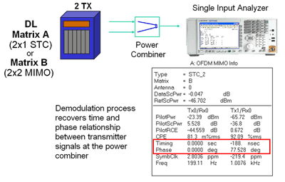
Fig. 6. By measuring the combined transmitter signals, a single input analyzer can make precise relative RF timing and phase measurements.
Conclusion
STC and MIMO multi-transmitter techniques can provide significant improvement in system performance in some environments, but their multiple channels present special challenges to the design engineer. Despite the multichannel nature of the signals, many useful and important measurements can be made by a single input analyzer. To make these measurements the analyzer takes advantage of special characteristics of the MIMO OFDMA signal, and in some cases even signal impairments such as crosstalk.
References
[1] “WiMAX Wave 2 Testing — MIMO & STC”, Agilent webcast, January 17, 2008 http://www.techonline.com/learning/livewebinar/204203534
[2] “Effects of physical layer impairments on OFDM systems” by Bob Cutler http://rfdesign.com/mag/radio_effects_physical_layer/
[3] “IEEE 802.16e WiMAX OFDMA Signal Measurements and Troubleshooting” Agilent Application Note 1578, Literature No. 5989-2382EN, June 2006.
Advertisement
Learn more about Agilent Technologies


