Smart grid metering and suitable architectures
A developer must choose the right smart grid architecture for each application
BY PETRE MINCIUNESCU
Analog Devices, Wilmington, MA
www.analog.com
The electric grid is a network formed of power plants, transmission lines, and consumers. In the future, the expectation is that the consumers will increase significantly their consumption of energy. The reason is that the appearance on the market of plug in electric vehicles increases enormously the daily energy consumption of the owner.
A car that has 24-kWh batteries and requires daily charging, may double or triple the monthly consumption of a household. As one can think more power plants will be added to supply this energy increase, the transmission lines are harder to upgrade. This is why the concept of smart grid was introduced: the transmission lines must be managed more intelligently, to allow the energy consumption to be with the lowest degree of harmonic pollution, distributed more evenly during the day and therefore keep up with the energy consumption increase.
The management of the smart grid means knowing in real time what in going on at the consumer level and on the transmission lines and this signifies from engineering perspective two things: one is that a lot of electrical quantities must be measured all the time and the other is that the utility must periodically communicate with the instrument measuring these quantities. This article looks at what electrical quantities must be monitored and studies various architectures to measure them.
Let’s consider an ac system supplied by a voltage v(t) that consumes the current i(t):

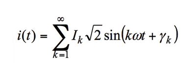
where Vk ,Ik = rms voltage and current of each harmonic, φk ,γk =phase delays of each harmonic, ω=2πf, the angular velocity of the fundamental.
Total active power. The active power is the average on the instantaneous power over an integral number of line cycles:

It is called “total” active power because it includes the contribution of the active powers on all harmonics. It is in the end what all consumers pay to the utility.
Fundamental active power . This power is the active power on the fundamental:

t is the only active power that should be exchanged between the consumer and the utility. It can be positive indicating the consumer uses, “consumes” the power and it can be negative, if the consumer generates it into the grid.
Harmonic active power. This power is the active power on one harmonic k:

This type of active power is important because it constitutes pollution and it should not exist in the grid. This is why in last few years, separating the fundamental active power from the harmonic active powers became very important. The sign of the harmonic active power shows who produces the pollution and who consumes it. Identifying who generates harmonic active power is important from smart grid perspective in order to eliminate the polluter.
Total, fundamental, and harmonic reactive powers . The reactive power is defined as the product of the voltage and current waveforms when all harmonic components of one of these signals are phase shifted by 90°:

It is a pure oscillatory power that has an average of 0. Similar to the active power, it can be total, fundamental or harmonic. The problem with the total reactive power is that it does not have a lot of practical significance and it has long been controversial. Therefore, the fundamental and harmonic reactive powers are mostly required to be measured.
RMS of currents and voltages represents the average over an integral number of line cycles of the squares of the current or voltage:
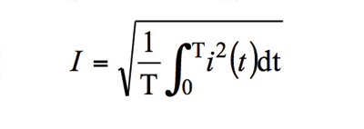
If the fundamental and harmonic components of the voltage and current are determined, the fundamental and harmonic rms values are also required.
Total, fundamental and harmonic apparent powers.
The apparent power is defined as the arithmetical product of the rms current and rms voltage and based on what rms values are used, it can be total, fundamental and harmonic.
These are the most important quantities that are measured. Additional quantities are: power factors, harmonic distortions, positive, negative and zero sequence powers in three phase systems.
The instruments measuring these quantities do not necessarily provide the performance of high-end power-line monitors, nor do they need to in most cases. As the requirements emerge, and as each new generation of semiconductor components gets cheaper, monitoring these quantities will become more pervasive across the grid. For example, it is difficult to imagine the need for an energy meter in residential apartments computing harmonic powers.
However, encouraging consumers to charge their electric vehicles at night, when the energy consumption is lowest, makes more sense from smart grid perspective. But an instrument that monitors all the quantities listed above at the substation level is definitely a requirement.
Monitoring a local industrial consumer to verify that the harmonic pollution is as low as possible makes a lot more sense because it is far more probable there is some industrial process injecting harmonics into the grid. From this point up into the grid hierarchy, similar instruments make perfect sense: all major substations and power lines are monitored. In the following, various systemic approaches to compute the quantities listed above are provided.
Standalone A/D converters, DSPs
The approach that provides the design engineer maximum flexibility is using A/D converters connected to a DSP (see Fig. 1 ). The DSP can be any processing machine suitable to sustain the computations mentioned above, so it can also be a microcontroller (MCU). This is why Fig. 1 shows a DSP integrated with a MCU. Of course, the number of A/D converters scales with the required number of currents and voltages that must be measured in the system.
A three-phase system may require measuring three-phase voltages, three-phase currents and one neutral current. A single phase system may require one phase voltage and one phase current. It is the most flexible system because the A/D converters and the DSP/MCU may be chosen independently, targeting the right degree of A/D converter accuracy and the right DSP characteristics for the particular application. The downside is that the developer must spend a lot of time implementing the metrology program, a nontrivial matter.
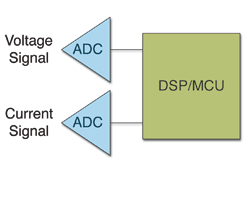
Fig. 1. Standalone A/D converters and a DSP/MCU.
DSP with embedded A/D converters
Using a DSP with embedded A/D converters (see Fig. 2 ) offers a lower degree of flexibility than the previous approach: not all standalone A/D converters have also been embedded with a DSP, and the DSPs embedded with A/D converters have certain clock frequencies, certain flash memory size, certain communication peripherals. But the cost is usually lower.
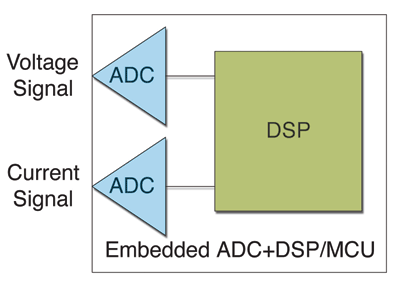
Fig. 2. DSP/MCU embedded with A/D converters.
AFE with a microcontroller
Using an analog front end (AFE) with a microcontroller (see Fig. 3 ) consists in an application-specific standard product (ASSP) that contains the right number of A/D converters for a particular single or poly phase metering application coupled with a metrology engine that computes all the metering quantities the system usually requires. The AFE is managed by an external microcontroller.
The advantages of this approach are: the MCU can be a lower grade relative to previously discussed cases as it does not need to compute all the metering quantities: this means a lower clock frequency, a lower flash memory size, etc.
The developer concentrates on managing the AFE and the external interfaces as all the energy metering quantities are guaranteed to be computed within the right specifications by the AFE developer. As the silicon manufacturers offer microcontroller families with various clock frequencies and flash memory sizes, the meter manufacturer can scale this architecture in a very efficient way.
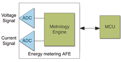
Fig. 3. Energy-metering AFE with MCU.
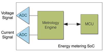
Fig. 4. Energy-metering system on a chip.
SoC
Using a system-on-chip that has an analog front end embedded with a microcontroller (see Fig. 4 ) takes the energy-metering analog front end and embeds it with a MCU. The advantage is that the meter has only one chip that does everything. The big disadvantage is that the developer looses the flexibility in choosing the right MCU for the particular specification. Therefore this architecture cannot be scaled easily. ■
Advertisement
Learn more about Analog Devices


