Pulse width modulation (PWM) control, which uses variable-width digital pulses to represent the amplitude of an analog waveform, has been around for decades. The first specialized PWM IC dates back to the SG1524 in 1976, and the technique is now widely used in numerous applications, including DC motor control, switch mode power supplies, Class D audio amplifiers, and LED brightness control.
PWM Overview
Pulse-width modulation uses a rectangular pulse wave whose pulse width is modulated resulting in the variation of the average value of the waveform.
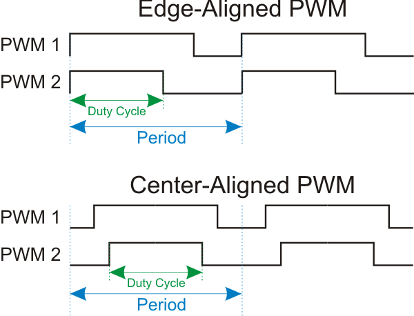
The period P is the time it takes for a signal to complete an on-and-off cycle. The duty cycle D is the portion of one period during which a signal is active (see Figure 1). As a percentage, D can be expressed as:

For a digital pulse waveform with maximum value Vmax, minimum value 0, and a duty cycle D (see figure 1), the average value, Vav, of the waveform is
Vav = D.Vmax
 Figure 1: Key PWM specifications (source: kerhuel.eu)
Many PWM applications, such as motor control, require multiple signals switching on and off in a phased sequence.
In edge-aligned PWM switching, all phases switch on simultaneously at the beginning of each period, but switch off at different times depending on the duty cycle of each phase. Multiple high current phases switching on simultaneously cause a much larger EMI transient than if the phases always change at different times.
Center-aligned switching activates the PWM outputs such that the centers of all the active periods are aligned, rather than the starts. For each phase output, half the duty cycle occurs before the center alignment reference and half after, thereby minimizing EMI.
Traditional PWM Implementations
Many standalone PWM ICs generate a signal using a purely analog approach – determining the master oscillator frequency with one external resistor, setting the base period with another, and varying the duty cycle with an analog control voltage is a typical technique. These have the advantage of simplicity, but are inflexible in operation and require expensive precision components for most accurate performance.
In the digital domain, microcontrollers have long included timers as a standard peripheral option – they have been used to generate PWM signals in conjunction with code snippets to initialize, set duty cycle, start and stop the PWM function. These offer more precise control of the PWM function, but require constant attention from the core, consuming resources and increasing power consumption.
Core-Independent PWM modules
Now, though, a new generation of smart PWM modules from Microchip are including advanced capabilities beyond those found in garden-variety PWM blocks.
The integrated 16-bit PWM modules are multi-function peripherals with the flexibility to be used in many applications. They can be optimized for precision, efficiency and EMI performance (center-aligned operation), or they can be configured as four additional 16-bit timers for general use.
Once configured, the peripherals run independent of the core for steady-state control, allowing the core to perform other tasks, or even go to sleep. Any of the 16-bit PWMs can be used with another Microchip feature, the Complementary Waveform Generator (CWG), which enables automated complementary output control with control of key parameters such as dead-band and auto-shutdown.
The new smart peripherals are available on the 8-bit PIC12F157X and PIC16F157X microcontroller families, which offer a range of features in packages ranging from 8 to 20 pins.
PWM block overview  Figure 2: Core-independent PWM block diagram (source: Microchip)
Figure 2 shows the operation of the PWM block. Each module in a device has its own independent timer driven by a selection of clock sources, four separate modes of operation, and four offset modes which allow adjustment of a slave module waveform relative to the waveform of a master PWM module in the same device.
Each PWM module has four independent interrupts based on the phase, duty cycle, period, and offset match events. With the appropriate selection of clock source, each PWM module will continue to operate when the microcontroller is in power-down (sleep) mode.
Full details can be found in the appropriate Microcontroller datasheet.
In the LED application example below, the 16-bit PWMs provide 216 (65,536) levels of brightness. With a clock frequency of 16MHz for the PIC12F1572 and a prescaler setting of 1, the PWM period is given by 16 x 106/65,536, or 244.1Hz. This is well above the 200Hz frequency at which the human eye can detect flicker, giving smooth operation.
Application Example: LED Lighting Control
In order to demonstrate the capabilities of the core-independent PWM block, Microchip has developed an RGB LED color mixing demo with the PWM drive for the red, green, and blue LEDs controlled by the PIC12F1572, which contains three 16-bit PWM blocks.
The demo features two modes of operation designed to produce a range of colors that appear on the CIE 1931 XY Chromaticity chart.
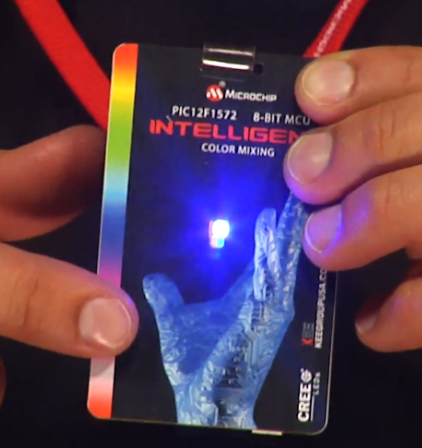
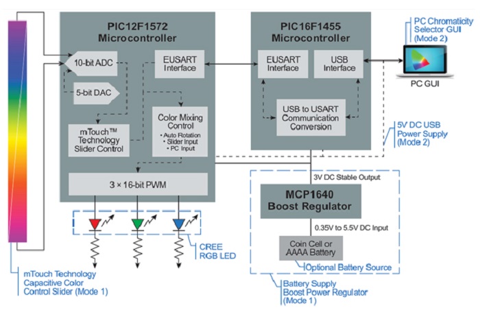
In Mode 1, the PWM duty cycle inputs care calculated based on the input from an mTouch capacitive slider; Figure 3 shows the mTouch slider (vertical strip at left) being used to change the LED color on the RGB badge.
Mode 2 makes use of a PC-based chromaticity selector GUI. The chromaticity application, communicating with the PIC12F572 via a PIC16F1455-based USB-to-serial converter, performs color calculations to generate the PWM duty cycle values required to reproduce the selected color on the RGBbadge.
 Figure 4: RGBbadge demonstration of the PIC12F1572 core-independent 16-bit PWM blocks (source: Microchip)
Figure 4 shows the block diagram for both Mode 1 and Mode 2 operation. The application note, schematic, source code, board layout and demonstration video can all be downloaded from the Microchip web site.
PWM hardware has come a long way since the SG1524 in 1976. The 16-bit PWM blocks discussed above are core-independent and designed to handle their tasks with no code or supervision from the CPU. As a result, they simplify the implementation of complex control systems and give designers the flexibility to innovate.
Advertisement
Learn more about Microchip Technology


