Introduction
Many solar-panel-powered applications need only pulses of power to operate. Systems for data collection or measurement sampling frequently need to turn on, perform a measurement or some other task, transmit the processed or measured data, and return to sleep. In many cases, wirelessly transmitting the data consumes the largest portion of output power. These required power pulses, either for the system itself or for transmitting data, typically are difficult to support with a power-limited supply such as a solar panel. By operating at the solar panel’s maximum power point (MPP) and by intelligently drawing the power from the panel, energy can be successfully harnessed to power a pulsed load. This article presents a simple and cost effective solution for maximum-power-point tracking (MPPT) for use in such pulsed-load systems.
Solar-panel characteristics
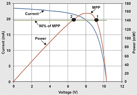
Solar panels provide peak output power when operated at their MPP. The MPP is a voltage and current corresponding to the panel’s highest obtainable output power. MPPT harnesses this power from a solar panel even as the amount of illumination varies. A characteristic of solar panels is that the panel voltage decreases as the current drawn from the panel increases. If the current drawn is too high, the voltage collapses and the amount of power drawn becomes very low. Figure 1 illustrates a particular solar panel’s output current and output power versus its output voltage. The MPP is labeled. A horizontal green line on the graph shows where the output power is at least 90% of the MPP. Above this line, between Points 1 and 2, the panel provides the most power.
When the solar-panel-powered load requires only pulses of power and does not need to be powered 100% of the time, one simple way to operate within 90% of the MPP is to turn on the load at Point 1 and turn it off at Point 2. When the load is on, it draws its required power, which lowers the panel voltage. This moves the operating point from Point 1, through the MPP point, and over to Point 2. At Point 2, the load is turned off and the panel voltage rises again. Even with this simple operation, there are three issues that must be overcome.
First, the load likely requires a different voltage than what the panel outputs. Thus, a high-efficiency power supply is required to convert the variable and relatively high panel voltage into a constant voltage for the load.

Figure 1: Graph of a solar panel’s MPP
Second, the panel voltage should be measured and the power supply disabled or enabled based on that voltage. Most power supplies have a digital input to enable or disable them. Such an input has a very imprecise threshold to differentiate a logic low from a logic high. With an imprecise threshold, the panel voltage cannot be wired directly to the enable input. Instead, an external circuit with a precise threshold is required. A supply-voltage supervisor can be used, but this adds the cost and complexity of a second device.
Third, the quickly changing panel voltage must be greatly slowed down to allow sufficient operating time to accomplish the required tasks. Changing the panel voltage from Point 1 to Point 2 requires almost no time—theoretically zero seconds. During this time, when the voltage varies from Point 1 to Point 2, the power supply for the load must turn on and the load must perform its task. This requires a power supply with a very fast turn-on and a long enough holdup of the panel voltage to perform the necessary tasks.
The MPPT solution
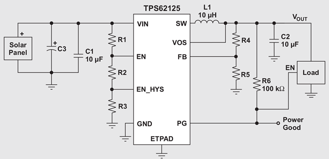
There are few single-device, cost-effective solutions that operate from the wide voltage range of power-limited solar-panel inputs while efficiently providing a regulated output voltage, a quick start-up, and operation within 90% of the MPP. However, the Texas Instruments TPS62125 is one such device that accepts input voltages of up to 17 V, operates with efficiencies in excess of 90%, starts up in less than 1 ms, and has an enable input pin with a precise threshold that can be directly wired to the solar panel’s voltage for MPPT. This eliminates the need for an additional device to perform this function. Figure 2 shows a complete solution.

Figure 2: MPPT circuit for a pulsed load
The voltage divider, formed by R1 and R2, is configured to turn on the power supply at Point 1 in Figure 1. Until the power supply is enabled, the device itself holds the node between R2 and R3 at ground potential. After the supply is enabled, the device releases this node, and R3 is then part of the voltage divider. When the solar-panel voltage falls to Point 2, the device turns off and holds the node low between R2 and R3 again. At this point, the panel voltage begins to rise again until it reaches the turn-on threshold. This provides a fully programmable turn-on and turn-off voltage that can be configured to any solar panel.
The bulk input capacitor, C3, stores enough energy from the solar panel to power the load for the required duration and provides the charge for starting up the power supply. The panel delivers a current corresponding to its voltage to either the power supply or C3. When the power supply is off, the solar panel delivers its current to the capacitor. When the power supply is on, the capacitor and solar panel provide the necessary current to power the load. Since C3 merely stores energy and this energy is released over a relatively lengthy period of time, C3 can be a low cost electrolytic capacitor.
Computing the required bulk input capacitance
The first step in designing the MPPT circuit is determining the load’s power needs and then computing the amount of required bulk input capacitance based on these power requirements and the chosen solar panel. As an example, assume a remote sensing circuit requires 3.3 V at 250 mA (825 mW) for a duration of 15 ms. These are typical needs for a system that contains a measurement device, a microprocessor, and an RF transmitter.
After the load’s power needs are determined, the required value for C3 is calculated. First, the input current required to power the load is found from Equation 1:

VIN is the average solar-panel voltage between Points 1 and 2 in Figure 1, and η is the power-supply efficiency at the given output power. Notice that the typical efficiency of the power supply at a VIN of about 7.8 V and an output power of 825 mW is around 87%. Using these numbers, IIN = 122 mA. This is much greater than what Figure 1 shows the solar panel to be capable of providing, so C3 must store enough energy to provide the remaining current for 15 ms. Equation 2 determines the required C3 value based on the load requirements and solar-panel characteristics:

VP1 and VP2 are the voltages at Points 1 and 2, which are respectively about 9 V and 6.5 V for this panel, and correspond to the voltage change across C3 as it discharges. The required load operating time, given by tON, is 15 ms. Finally, IPanel(Avg) is the average current from the solar panel when the panel is operated within 90% of its MPP. As seen in Figure 1, this current is about 19 mA.
From Equation 2, it is determined that C3 should be greater than 618 μF. A 680-μF capacitor is used to provide some margin in the operating time.
Calculating the enable pin’s voltage divider
R1, R2, and R3 form a fully configurable voltage divider with hysteresis for the enable (EN) pin. Equations 3 and 4 are used to set the resistor values: 

R1 is chosen first, and 1 MΩ is a good starting value. With this, R2 is calculated to be 153.8 kΩ. The closest standard value of 154 kΩ is chosen. R3 should be 60.9 kΩ, and 60.4 kΩ is the nearest standard value.
Additional MPPT circuit configuration
Another feature that can be configured to benefit the typical application is using the power good (PG) output to control the load’s enable (EN) input. The PG pin is held low when the power supply is off. The pull-up resistor, R6, pulls it high, but only when the power supply is enabled and the output voltage is in regulation. Connecting the PG output directly to the load’s EN input keeps the load disabled until the input voltage has risen above VP1 and until the output voltage is high enough to properly power the load. As the power supply is disabled from the input voltage falling below VP2, the PG pin is actively pulled low, which also disables the load. This configuration ensures that the load is enabled only when its supply voltage is in regulation, avoiding a low supply voltage that possibly could corrupt the load’s performance or data.
Operation of MPPT circuit within 90% of MPP

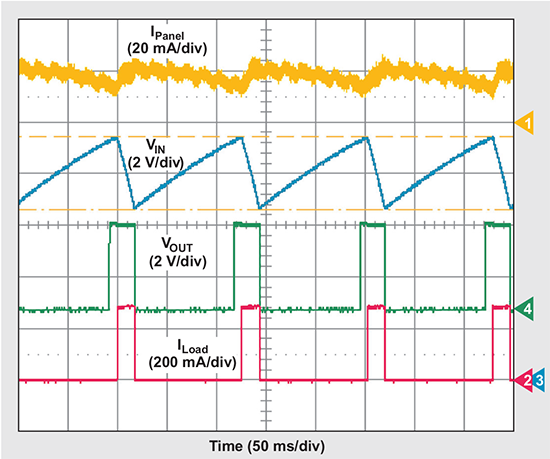
Figure 3: Operation of MPPT circuit within 90% of MPP
Test results
Figure 3 shows the MPPT circuit in operation. The panel voltage, VIN, remains between 9 V and 6.5 V (VP1 and VP2, respectively). Once VOUT enters regulation, the load enables and draws 250 mA. When the panel’s voltage drops to 6.5 V, VOUT is disabled and thereby disables the load current. The solar panel provides an average of 19 mA at all times. The load has a run time of around 18 ms in Figure 3, meeting the 15-ms requirement. This run time roughly matches the calculations, since the value of C3 increased above the result of those calculations.
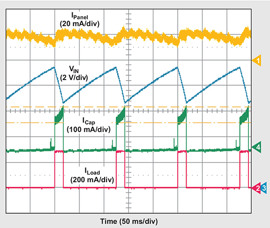
Figure 4 replaces the output-voltage trace in Figure 3 with the trace for ICap, the current from C3. As VIN decreases, the current leaving the capacitor is positive—the capacitor provides its stored energy to the power supply, which then supplies that energy to the load. Once the load turns off, due to the panel voltage decreasing to 6.5 V and the power supply disabling, the current from C3 goes negative—the capacitor recharges from the panel and stores energy for the next cycle. The current from C3 spikes briefly before the load is enabled, as the power supply turns on when the panel voltage is sufficiently high. Additional input current provided by C3 is needed during start-up.

Figure 4: Bulk input capacitor (C3) supplying a circuit operating within 90% of MPP
Conclusion
This article has demonstrated a simple and cost effective circuit for tracking a solar panel’s MPP for a pulsed-load system, such as a remote measurement system that transmits its data via RF transmitters. This topology also can be configured to any solar panel and any pulsed load.
Advertisement
Learn more about Mouser Electronics


