Design Considerations
Solar Power Inverter
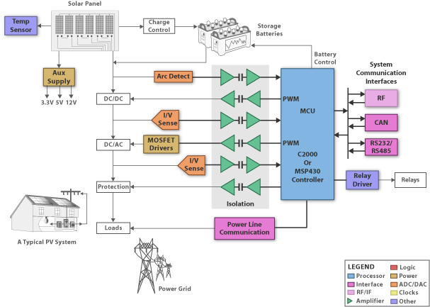
The solar inverter is a critical component in a solar energy system. It performs the conversion of the variable DC output of the Photovoltaic (PV) module(s) into a clean sinusoidal 50- or 60 Hz AC current that is then applied directly to the commercial electrical grid or to a local, off-grid electrical network. Typically, communications capability is included so users can monitor the inverter and report on power and operating conditions, provide firmware updates and control the inverter grid connection. Depending on the grid infrastructure wired (RS-485, CAN, Power Line Communication, Ethernet) or wireless (Bluetooth, ZigBee/IEEE802.15.4, 6loWPAN) networking options can be used.
At the heart of the inverter is a real-time microcontroller. The controller executes the very precise algorithms required to invert the DC voltage generated by the solar module into AC. This controller is programmed to perform the control loops necessary for all the power management functions necessary including DC/DC and DC/AC. The controller also maximizes the power output from the PV through complex algorithms called maximum power point tracking (MPPT). The PV maximum output power is dependent on the operating conditions and varies from moment to moment due to temperature, shading, soilage, cloud cover, and time of day so tracking and adjusting for this maximum power point is a continuous process. For systems with battery energy storage, the controller can control the charging as well as switch over to battery power once the sun sets or cloud cover reduces the PV output power. The controller contains advanced peripherals like high precision PWM outputs and ADCs for implementing control loops. The ADC measures variables, such as the PV output voltage and current, and then adjusts the DC/DC or DC/AC converter by changing the PWM duty cycle.
The C2000 in particular is designed to read the ADC and adjust the PWM within a single clock cycle, so real time control is possible. Communications on a simple system can be handled by a single processor, more elaborate systems with complex displays and reporting on consumption and feed-in-tariff pay back may require a secondary processor, potentially with ethernet capability like the Stellaris Cortex M3 parts. For safety reasons, isolation between the processor and the current and voltage is also required, as well as on the communications bus to the outside world.
The Safety MCUs offer an ARM Cortex-R4F based solution and are certified suitable for use in systems that need to achieve IEC61508 SIL-3 safety levels. These MCUs also offer integrated floating point, 12 bit ADCs, motor-control-specific PWMs and encoder inputs via its flexible HET Timer co-processor. Hercules Safety MCUs can also be used to implement scalar and vector-control techniques and support a range of performance requirements.
Download Full Block Diagram Below
Advertisement

Learn more about Texas Instruments


